Methods, apparatus, and systems for monitoring and/or controlling dynamic environments

a dynamic environment and apparatus technology, applied in the direction of electrical programme control, program control, instruments, etc., can solve the problems of excessive latencies of conventional programmable logic controllers (plcs) for monitoring and/or controlling some types of dynamic environments, processor-based control devices employing a general-purpose computer architecture, and conventional plcs as well as other more general-purpose computers are often not appropriately suited for applications involving monitoring and/or controlling dynamic environments. , to achieve the effect o

Inactive Publication Date: 2019-02-07
OPTEON
View PDF0 Cites 8 Cited by
  • Summary
  • Abstract
  • Description
  • Claims
  • Application Information

AI Technical Summary

Benefits of technology

[0038]In view of the foregoing, in other co-processor implementations according to various embodiments of the invention, a significantly streamlined special-purpose co-processor includes pared-down digital logic to specifically implement a comparator function (e.g., the functional equivalent of an IF THEN statement) based on the contents of the co-processor's dedicated memory and the monitored input signals; in essence, the functional capability of the co-processor is reduced to the particular evaluation of a single condition via a significant reduction in hardware. Such a co-processor implementation accomplishes the goal of a low-cost, space-saving, low-latency solution. In exemplary implementations, several such co-processors may be implemented inexpensively in a field programmable gate array (FPGA), an application specific integrated circuit (ASIC), or a fully-customized circuit, for example.
[0039]In one aspect of a streamlined co-processor implementation as discussed above, to alternatively or further facilitate low latency, a particular memory structure is employed for the co-processor's dedicated memory to store information in the form of a “condition / action pair.” In one example of such a memory structure, a condition / action pair comprises particular data stored in a memory location (e.g., a single memory register, or multiple adjacent memory registers) arranged as a first number of bits representing the condition to be evaluated, and a second number of bits representing an action to be taken if the condition is satisfied. Such a memory structure facilitates a straightforward and relatively simple digital logic implementation to compare monitored input signals to the first number of bits representing the condition to be evaluated and, if there is a match (i.e., the condition is satisfied), provide the second number of bits representing the corresponding action to be taken as a gated output of the co-processor. Accordingly, based on structured memory contents constituting a “condition / action pair” and relatively simple digital logic implementing a comparator and a gate to provide a gated output, and effective low-latency, low-footprint, and low-cost co-processor may be realized.

Problems solved by technology

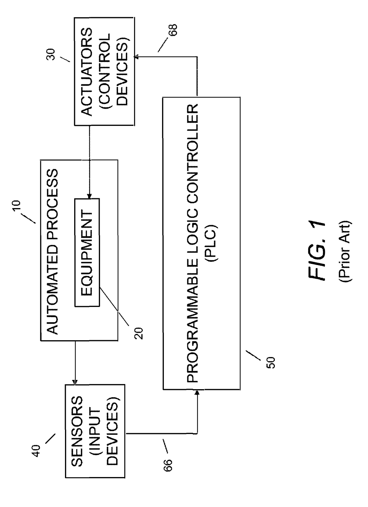
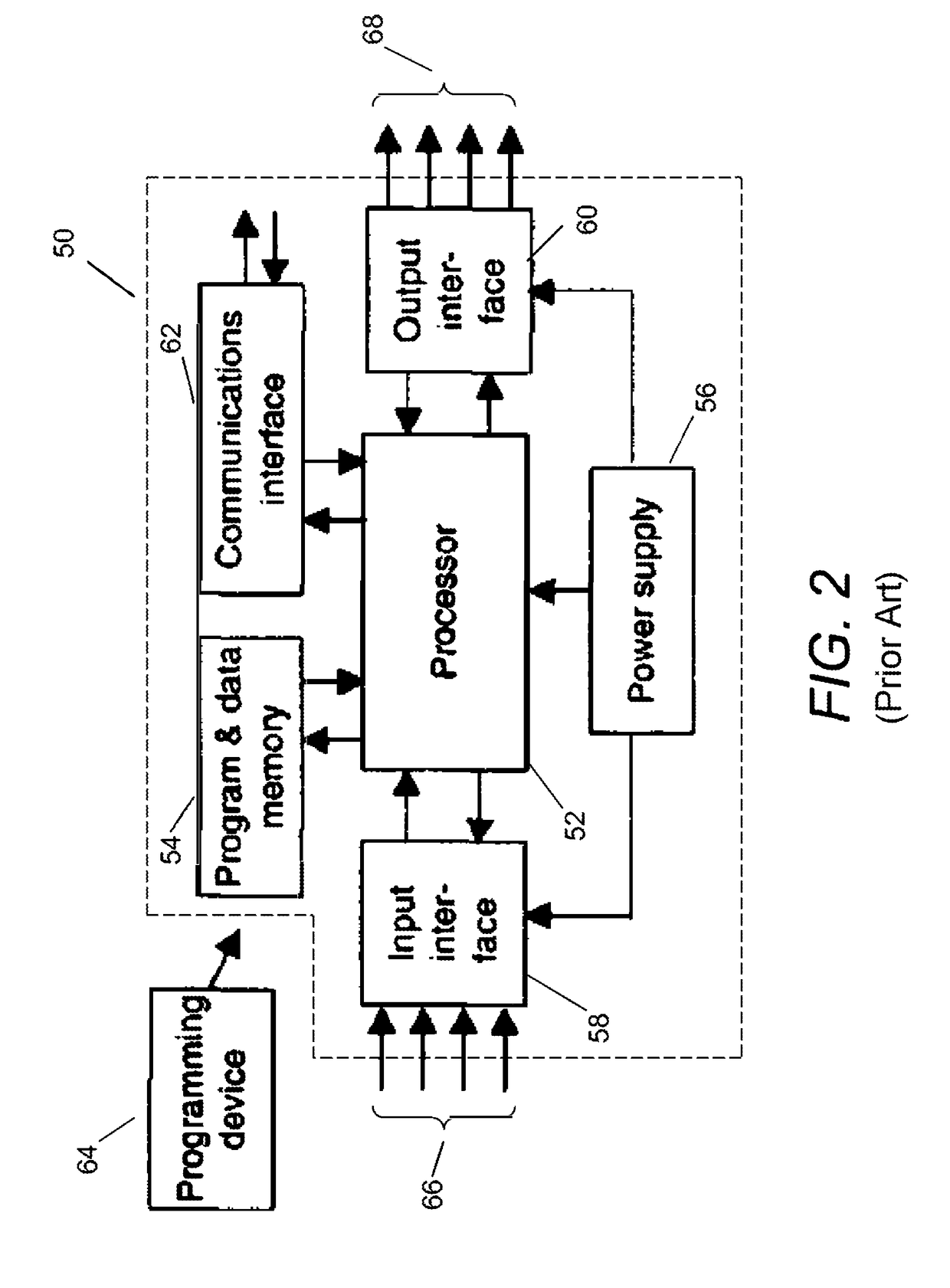
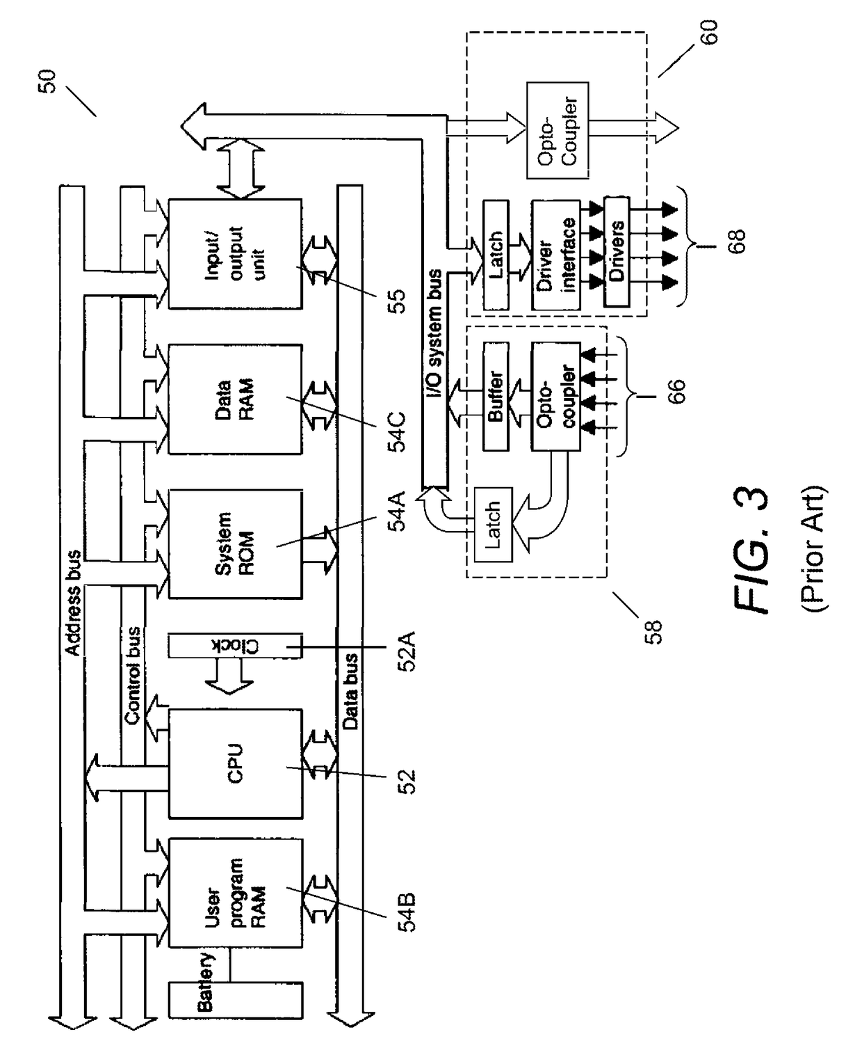
The Inventors have recognized and appreciated that typical latencies associated with conventional programmable logic controllers (PLCs) may be excessively long for monitoring and / or controlling some types of dynamic environments (e.g., involving automated systems and / or processes).
More generally, conventional PLCs as well as other more general-purpose computers often are not appropriately suited for applications involving monitoring and / or controlling dynamic environments in which significant speed and / or precision is / are required in connection with response or reaction time (e.g., taking some action, such as controlling equipment, machinery and / or instrumentation, in response to one or more monitored conditions).
In particular, processor-based control devices employing a general-purpose computer architecture (or related computer architectures with a small and finite set of general purpose processors), and executing programs sequentially or cyclically, are not sufficiently fast to implement control functions in dynamic environments that require reflex-like reactions in response to evolving conditions of the environment, which may benefit from essentially simultaneous evaluation of multiple possible conditions and taking immediate action based on same.

Method used


Image

  • Methods, apparatus, and systems for monitoring and/or controlling dynamic environments
  • Methods, apparatus, and systems for monitoring and/or controlling dynamic environments
  • Methods, apparatus, and systems for monitoring and/or controlling dynamic environments

Examples


example 1

Continuous One-State Process

[0135]

continuous process send_on_edge with instances i := 0..7beginwait for rising edge of input i# state (condition no. 1)send sender i# action (executed by co-processor)end

[0136]Example 1 is a continuous process, called “send_on_edge,” in which a co-processor is tasked with waiting for a rising edge (the condition) of input i and sending a packet (the action) to another device upon satisfaction of the condition. The co-processor also notifies the master processor that its condition has been met upon detecting the rising edge. In this example, once the co-processor has sent the packet, the master processor reloads the same condition and action opcode pair in the co-processor's memory. The co-processor continues to monitor the rising edge of input i until the co-processor is halted or interrupted, e.g., by the master processor 190. This process is implemented eight times (i=0 . . . 7), with each instance running on a separate slot in the action engine or ...

example 2

Continuous Two-State Process

[0137]

continuous process send_on_pulse with instances i := 0..7beginwait for rising edge of input i # state no. 1 (condition no. 1)send sender i# action no. 1a (executed by co-processor)set output i+8# action no. 1b (also executed by co-processor)wait for 100ms# state no. 2 (condition no. 2)clear output i+8# action no. 2 (executed by co-processor)end

[0138]Example 2 is a continuous process, called “send_on_pulse,” in which a co-processor alternates between two states depending on the evolution of the dynamic environment. In the first state, the co-processor waits for a rising edge to appear on input i as in Example 1 (this is the first condition of this process). Once the co-processor detects the input, it sends a packet to another device and notifies the master processor that the first condition has been met as above. It also performs another action—it sets output i+8—before proceeding to its second state (“wait for 100 ms”). In this second state, the co-...

example 3

Continuous Process with Master Processor Action

[0140]

continuous process send_sequence with instances i := 0..7beginstatic unsigned integer sequence := 0# declarationpayload p; # declarationp.dword[0] := sequence; # master processor actionwait for rising edge of input i# condition no. 1send sender i with payload p # action no. 1a (co-processor)sequence++; # action no. 1b (master processor)wait for sender to finish # condition no. 2; action 2 is a no-opend

[0141]Example 3 is another continuous process, entitled “send sequence,” in which a co-processor monitors conditions and the co-processor and the master processor each execute actions in response to detection of the conditions. In this case, the process begins with the declaration of a static variable named “sequence” (“static unsigned integer sequence”) and a 16-byte payload p that goes out with every event packet. Once these have been initialized, the master processor sets a word (“p.dword”) in the payload to the value of the “sequ...


PUM


Abstract

A dynamic environment (e.g., an automated industrial process) has multiple conditions in response to which corresponding actions are required, and comprises various equipment, control device(s) to control the equipment, and one or more sensors to generate input signal(s) representing a monitored condition of the environment. A control system for the environment comprises a master processor and one or more co-processors, wherein the master processor configures a given co-processor to evaluate only a first subset of conditions expected to occur in the environment within a specified time period (e.g., less than a response time of the master processor), and to provide first control information representing an action to be taken if a particular condition of the first subset is satisfied. The co-processor receives the input signal(s) representing the monitored condition, processes the input signal(s) so as to determine if the particular condition of the first subset is satisfied, and provides the first control information to the control devices so as to control the equipment. Exemplary applications include dynamic environments in which machine vision techniques and/or equipment are employed.

Description

CROSS-REFERENCE TO RELATED APPLICATIONS[0001]The present application is a continuation of U.S. non-provisional application Ser. No. 15 / 283,980, filed Oct. 3, 2016, entitled “Methods, Apparatus, And Systems For Monitoring And / Or Controlling Dynamic Environments,” which claims priority benefit under 35 U.S.C. § 120 to U.S. non-provisional application Ser. No. 13 / 646,326, filed on Oct. 5, 2012, entitled “Methods, Apparatus, And Systems For Monitoring And / Or Controlling Dynamic Environments,” which in turn claims a priority benefit, under 35 U.S.C. § 119(e), to U.S. provisional application Ser. No. 61 / 543,680, filed on Oct. 5, 2011, entitled “Methods, Apparatus and Systems for Monitoring and / or Controlling Dynamic Environments.” All of the aforementioned applications are hereby incorporated herein by reference in their entirety.BACKGROUND[0002]A programmable logic controller (PLC) is a special form of computer-based controller typically employed to control equipment, machinery and / or in...

Claims


Application Information

Patent Timeline
Patent Type & Authority Applications(United States)
IPC IPC(8): G05B19/042G06F11/20G06F11/07G05B19/05G05B15/02G05B13/02
CPCG06F11/07G06F11/2005G05B19/054G05B19/0423G05B19/052G05B19/0426G05B19/0421G05B15/02G05B13/021G05B2219/1153G05B2219/2214G05B2219/2231G05B19/0428
Inventor FRAZER, MARK J.HOPKINS, T. ERICSCHAEFFER, TIMOTHY N.
Owner OPTEON
Why Eureka
Try Eureka