Method for rigidity enhancement and weight reduction using laser peening

a technology of laser peening and rigidity enhancement, which is applied in the field of aerospace component design, can solve the problems that the potential for lightweight design of components has not been fully developed, and achieve the effects of weight reduction, rigidity enhancement, and weight reduction

Active Publication Date: 2019-02-07
GUANGDONG UNIV OF TECH
View PDF0 Cites 13 Cited by
  • Summary
  • Abstract
  • Description
  • Claims
  • Application Information

AI Technical Summary

Benefits of technology

[0018]The method for rigidity enhancement and weight reduction using laser peening provided by the present disclosure includes the following steps: performing the structural design on the component, and determining the limit size of the component; intercepting the component by adopting the material having the same trade mark and in the as-heat-treated state, performing the laser peening strengthening test on the component, and setting the multiple groups of strengthening parameters; performing the material performance test on the component, and acquiring the material performance improvement data; determining the topological optimization strengthening region, building the mathematical model, setting the target function and the constraint condition, and solving the area, the number and the layout form of the laser peening strengthening region by adopting the finite element; optimizing the cross-sectional size of the component according to the material performance improvement data; and estimating the static/dynamic strength, rigidity, bearing capacity and reliability indexes of the optimized component, judging whether design requirements

Problems solved by technology

However, the current structural lightweight design mainly focuses on the theoretical directions of algorithms such as the topological optimization and the size optimization of spatial structures of components, so that there is no information feedback in a design stage and a manufacturing stage, and the po

Method used


Image

  • Method for rigidity enhancement and weight reduction using laser peening
  • Method for rigidity enhancement and weight reduction using laser peening
  • Method for rigidity enhancement and weight reduction using laser peening

Examples


Embodiment Construction

[0025]The main idea of the present disclosure is to provide a method for rigidity enhancement and weight reduction using laser peening used for improving the performance of a component and realizing weight reduction of the component, thereby improving the comprehensive performance of a spacecraft or an aircraft.

[0026]In order to make those skilled in the art understand the solution of the present disclosure better, the present disclosure is further described in detail below with reference to the drawings and specific embodiments.

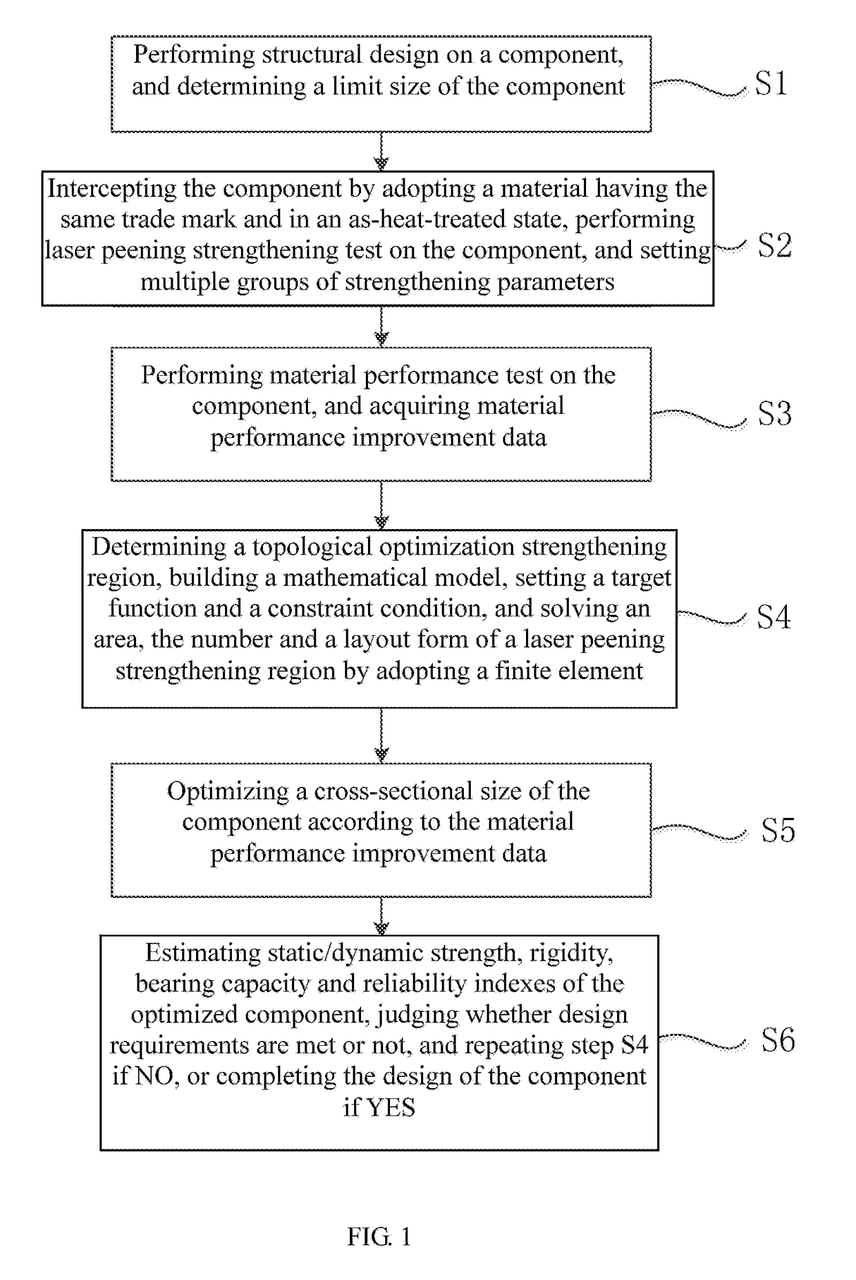
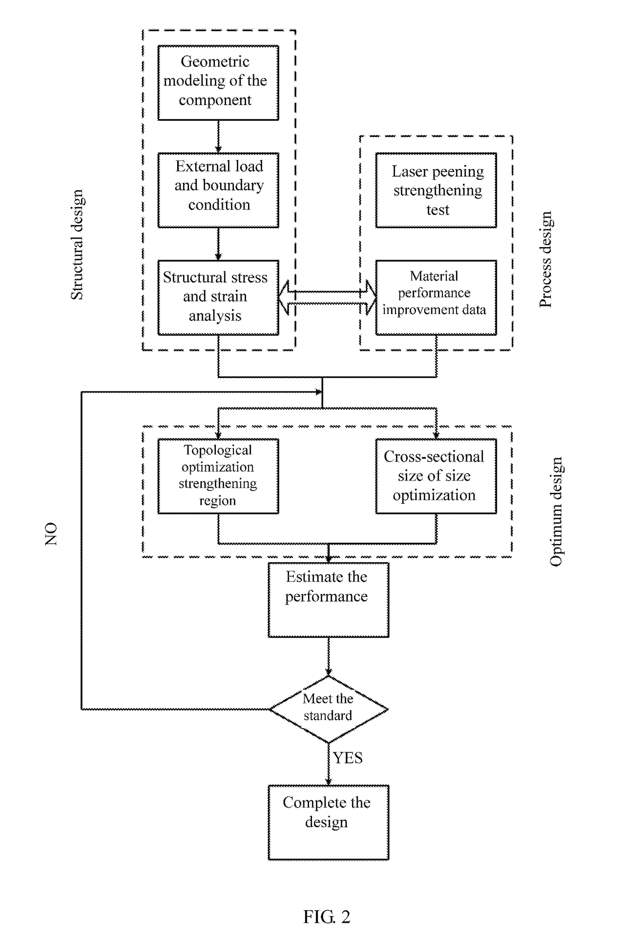
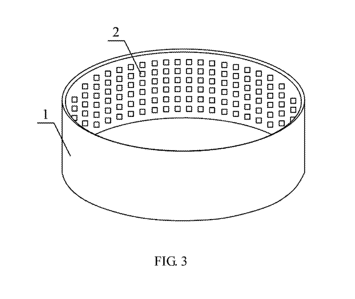
[0027]Referring to FIGS. 1 to 4, FIG. 1 is a flow chart a method for rigidity enhancement and weight reduction using laser peening according to a specific embodiment of the present disclosure. FIG. 2 is a schematic diagram of a method for rigidity enhancement and weight reduction using laser peening according to a specific embodiment of present disclosure. FIG. 3 is a structural schematic diagram of an aluminum alloy single-skin grating integral panel of a s...


PUM


Abstract

A method for rigidity enhancement and weight reduction using laser peening, includes the following steps: determining a limit size of a component; performing laser peening strengthening test on the component, and setting multiple groups of strengthening parameters; performing material performance test on the component, and acquiring material performance improvement data; determining a topological optimization strengthening region; optimizing the cross-sectional size of the component according to the material performance improvement data; and estimating static/dynamic strength, rigidity, bearing capacity and reliability indexes of the optimized component, judging whether design requirements are met or not, and repeating the step of determining the topological optimization strengthening region if NO, or completing the design of the component if YES.

Description

CROSS-REFERENCE TO RELATED APPLICATIONS[0001]This application is a continuation of International Patent Application No. PCT / CN2017 / 094099 with a filing date of Jul. 24, 2017, designating the United States, now pending, and further claims priority to Chinese Patent Application No. 201710285284.7 with a filing date of Apr. 25, 2017. The content of the aforementioned applications, including any intervening amendments thereto, are incorporated herein by reference.TECHNICAL FIELD[0002]The present disclosure relates to the field of aerospace component design, and particularly to a method for rigidity enhancement and weight reduction using laser peening.BACKGROUND OF THE PRESENT INVENTION[0003]Optimum structural design is to find a best design solution according to a certain objective (such as a lightest weight, lowest cost and highest stiffness) under a specified constraint condition, and was known as best structural design or optimal structural design before. Relative to “structural anal...

Claims


Application Information

Patent Timeline
IPC IPC(8): G06F17/50
CPCG06F17/5018G06F17/5095G06F2217/02G06F2217/16G06F2217/06G06F2111/06G06F2111/04G06F30/15G06F30/23G06F2111/10G06F2111/20
Inventor ZHANG, YONGKANGZHANG, ZHENG
Owner GUANGDONG UNIV OF TECH
Why Eureka
Try Eureka