Electric power converting apparatus

a technology of converting apparatus and electric power, which is applied in the direction of dc-ac conversion without reversal, electric apparatus casing/cabinet/drawer, transportation and packaging, etc., can solve problems such as damage to mounted parts, and achieve high-density mounting, increase vibration resistance, and reduce the effect of siz

Active Publication Date: 2019-02-14
MITSUBISHI ELECTRIC CORP
View PDF0 Cites 0 Cited by
  • Summary
  • Abstract
  • Description
  • Claims
  • Application Information

AI Technical Summary

Benefits of technology

[0012]According to the present invention, the first controlling circuit board and the second controlling circuit board are electrically connected on facing inner planes of the first controlling circuit board and the second controlling circuit board. Thus, because circuits for gathering signals to one side of the first controlling circuit board and the second controlling circuit board are no longer required, parts can be mounted on the first controlling circuit board and the second controlling circuit board efficiently, enabling the first controlling circuit board and the second controlling circuit board to be reduced in size.
[0013]The first controlling circuit board and the second controlling circuit board are fixed to the cooler or the housing using different fixing members. Thus, the position of fixing of the first controlling circuit board within the inner plane can be set independently from the position of fixing of the second controlling circuit board within the inner plane. Similarly, the position of fixing of the second controlling circuit board within the inner plane can be set independently from the position of fixing of the first controlling circuit board within the inner plane. Because the position of fixing of the first controlling circuit board and the position of fixing of the second controlling circuit board can be set independently in this manner, even if the positions of the antinodes of vibration of th...

Problems solved by technology

Among the parts that are mounted to the electric power converting apparatus, since the controlling circuit board in particular is thin and has a large area c...

Method used


Image

  • Electric power converting apparatus
  • Electric power converting apparatus
  • Electric power converting apparatus

Examples


embodiment 1

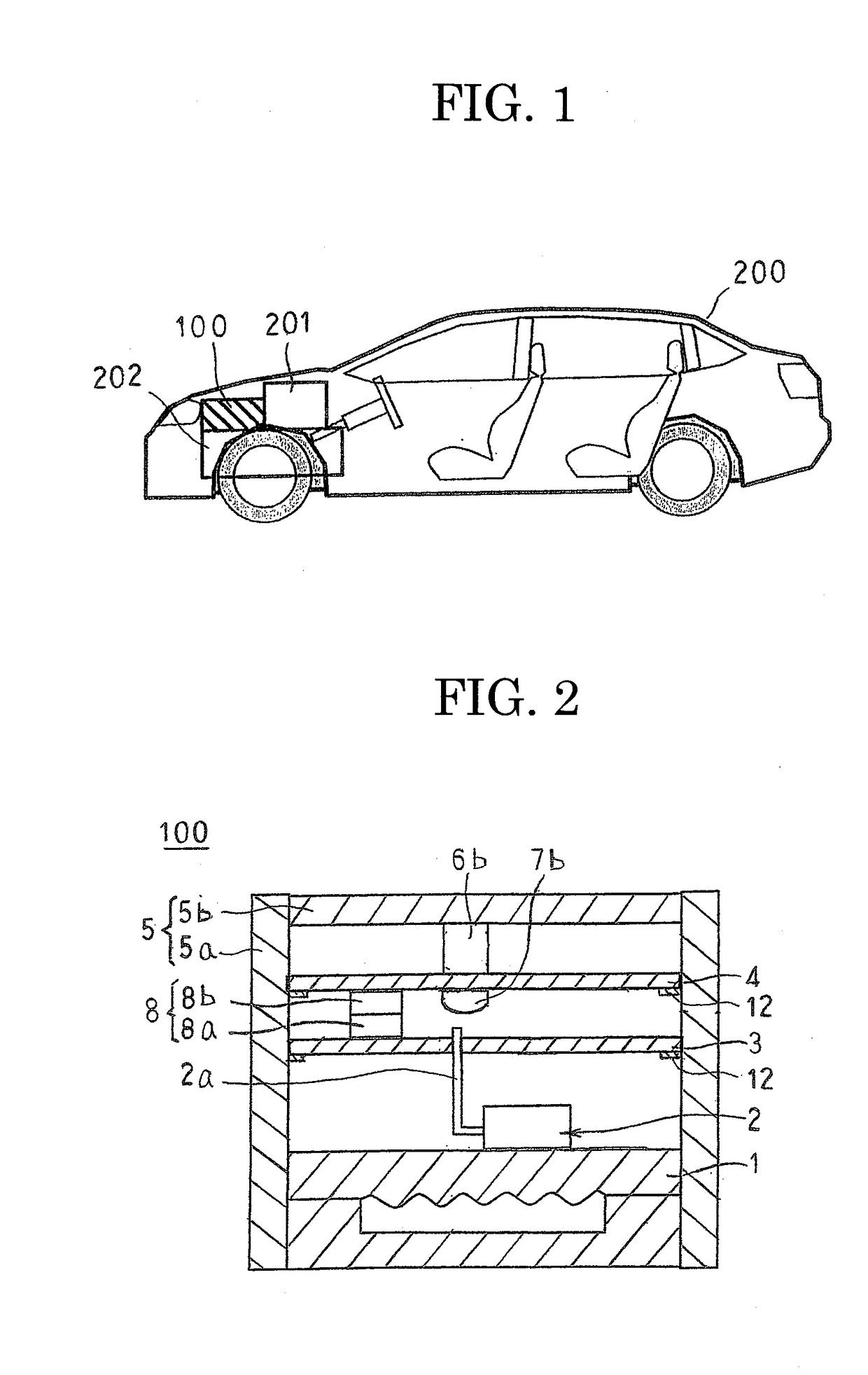
[0025]FIG. 1 is a schematic diagram that shows an automobile to which is mounted an electric power converting apparatus according to Embodiment 1 of the present invention, FIG. 2 is a cross section that schematically shows a construction of the electric power converting apparatus according to Embodiment 1 of the present invention, and FIG. 3 is a transparent oblique projection that schematically shows the construction of the electric power converting apparatus according to Embodiment 1 of the present invention.

[0026]As shown in FIG. 1, an electric power converting apparatus 100 is mounted above a transaxle 202 inside an engine compartment on which vibrational loads from an engine 201 of an automobile 200 and from a road surface easily act, for example.

[0027]Next, configuration of the electric power converting apparatus 100 will be explained with reference to FIGS. 2 and 3.

[0028]The electric power converting apparatus 100 includes: a power module 2 that incorporates a plurality of po...

embodiment 2

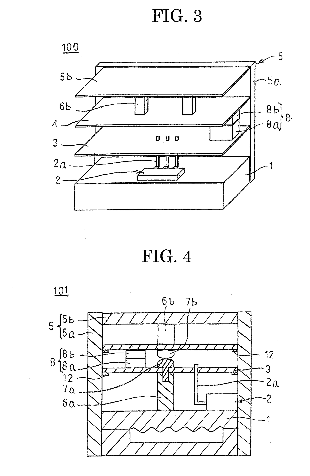
[0050]FIG. 4 is a cross section that schematically shows a construction of an electric power converting apparatus according to Embodiment 2 of the present invention, and FIG. 5 is a transparent oblique projection that schematically shows the construction of the electric power converting apparatus according to Embodiment 2 of the present invention.

[0051]In FIGS. 4 and 5, first supporting posts 6a are fixed to an upper surface of a cooler 1 using a solder, a sintered material of silver nanoparticles, a liquid phase diffusion binder such as copper-tin, silver-tin, etc., an adhesive, or screws, etc. A first controlling circuit board 3 is fixed to the cooler 1 by means of the first supporting posts 6a by being fixed by screws 7b to the first supporting posts 6a. The first supporting posts 6a constitute a first fixing member.

[0052]Moreover, a remainder of the configuration is configured in a similar or identical manner to that of Embodiment 1 above.

[0053]In an electric power converting ap...

embodiment 3

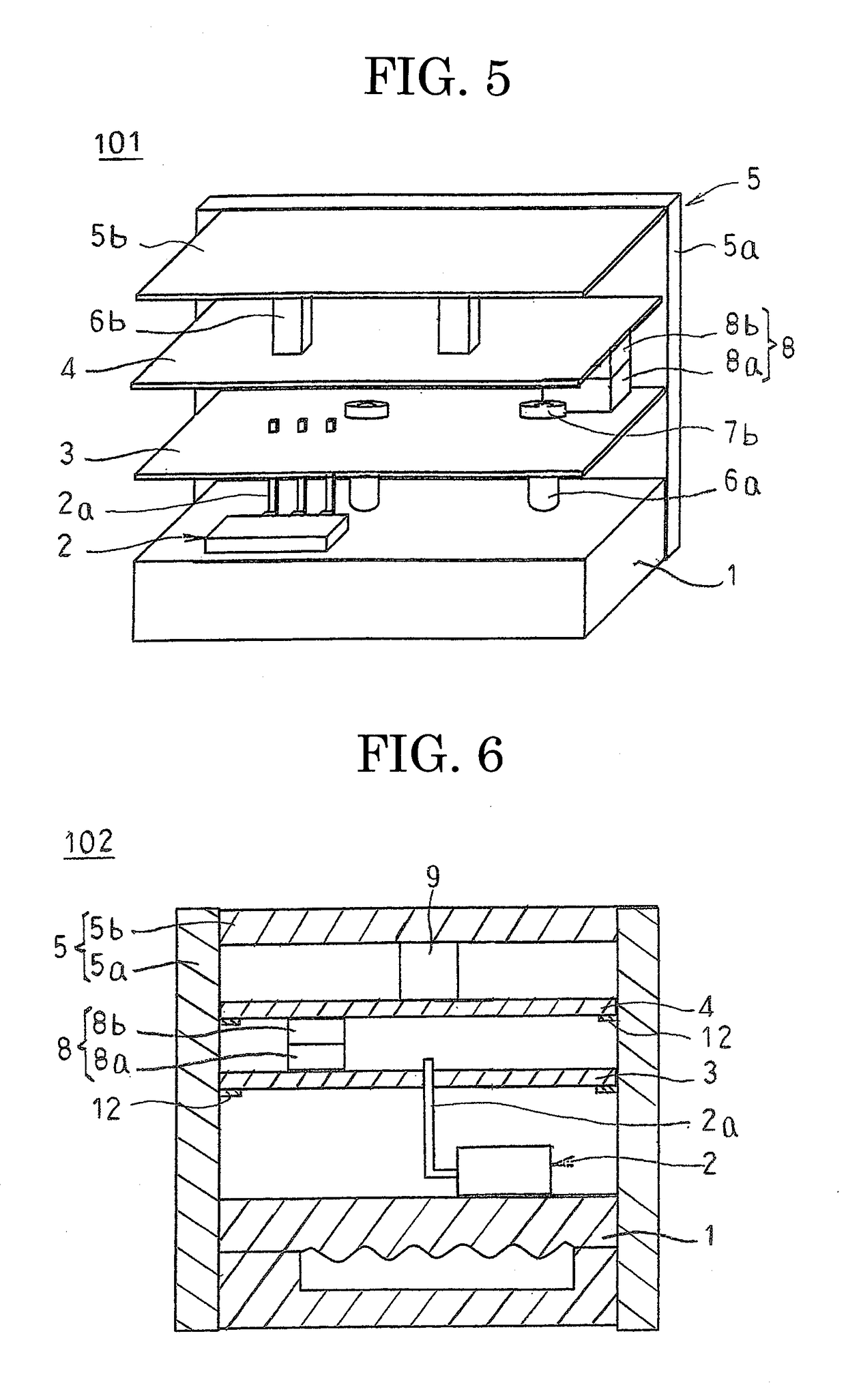
[0059]FIG. 6 is a cross section that schematically shows a construction of an electric power converting apparatus according to Embodiment 3 of the present invention, and FIG. 7 is a transparent oblique projection that schematically shows the construction of the electric power converting apparatus according to Embodiment 3 of the present invention.

[0060]In FIGS. 6 and 7, surface mounted components 9 that are mounted to an inner plane of a second controlling circuit board 4 are fixed to a lower surface of the cover portion 5b by adhesive. The surface mounted components 9 constitute a second fixing member.

[0061]Moreover, a remainder of the configuration is configured in a similar or identical manner to that of Embodiment 1 above.

[0062]In an electric power converting apparatus 102 according to Embodiment 3, the first controlling circuit board 3 is fixed to the cooler 1 by means of the signal terminals 2a of the power module 2, and the second controlling circuit board 4 is fixed to the c...


PUM


Abstract

An electric power converting apparatus includes: a first controlling circuit board disposed inside a housing; and a second controlling circuit board disposed inside the housing on an opposite side of the first controlling circuit board from a power module, wherein: an inner plane of the first controlling circuit board is fixed to a cooler or the housing by a first fixing member on an opposite side of the first controlling circuit board from the second controlling circuit board; an inner plane of the second controlling circuit board is fixed to the housing by a second fixing member on an opposite side of the second controlling circuit board from the first controlling circuit board; and the first controlling circuit board and the second controlling circuit board are electrically connected on facing inner planes of the first controlling circuit board and the second controlling circuit board.

Description

TECHNICAL FIELD[0001]The present invention relates to an electric power converting apparatus that converts electric power from a battery into electric driving power that is supplied to an electric motor of an automobile, for example.BACKGROUND ART[0002]In electric vehicles powered by an electric motor, and hybrid vehicles that are powered using a combination of an electric motor and an internal combustion engine, etc., an electric power converting apparatus is mounted that converts electric power from a battery into electric driving power that is supplied to the electric motor, for example. The electric power converting apparatus includes: electrical components such as a power module that includes switching elements such as insulated gate bipolar transistors (IGBTs), a cooler that radiates generated heat from the power modules, a controlling circuit board that controls driving of the power module, etc.; and a housing that houses the electrical components, and that protects the elect...

Claims


Application Information

Patent Timeline
IPC IPC(8): H02M7/48H05K7/14H05K5/00B60L11/00H05K7/20
CPCH02M7/48H05K7/14B60L2200/26H02M7/003H05K7/20H05K5/0026B60L11/00H05K7/1432H05K7/209B60L50/00
Inventor HAYASHI, KOMEI
Owner MITSUBISHI ELECTRIC CORP
Why Eureka
Try Eureka