Construction BIM, as-built geometry measurement, material
condition evaluation, and subsurface utility location are each frequently difficult to address prior to or during construction.
Previously, many separate processes and manual resources were required to perform surface+subsurface
metrology, including complex, inadequate and error prone subsurface
engineering surveys, manual
documentation, hand digging, material vacuuming, and many more repetitive processes and procedures.
While
Ground Penetrating Radar (GPR) can be an effective tool to perform non-invasive inspections, major issues with current techniques include time-consuming, complex and error-prone data collection, terrestrial measurement constraints, and
application specific analysis only reliably performed by specialists.
To date, an effective technology to consistently address these challenges has been elusive.
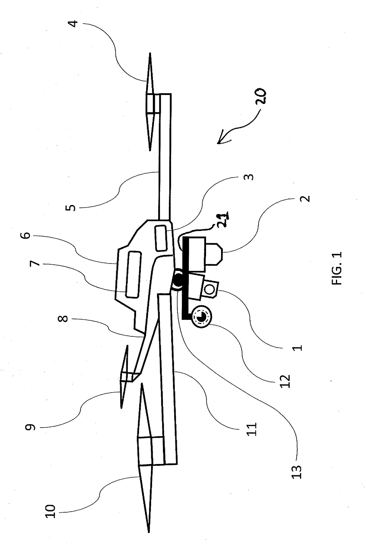
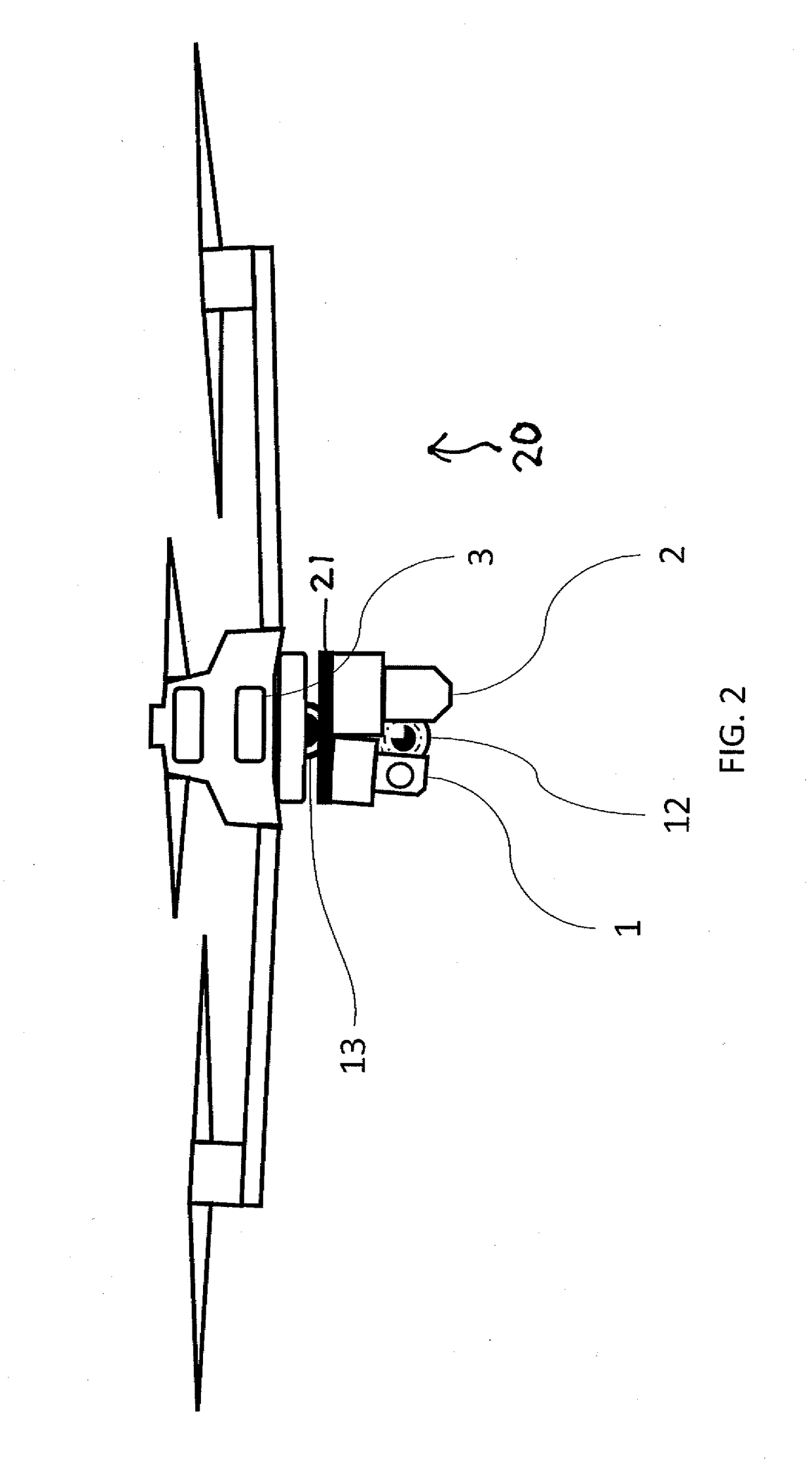
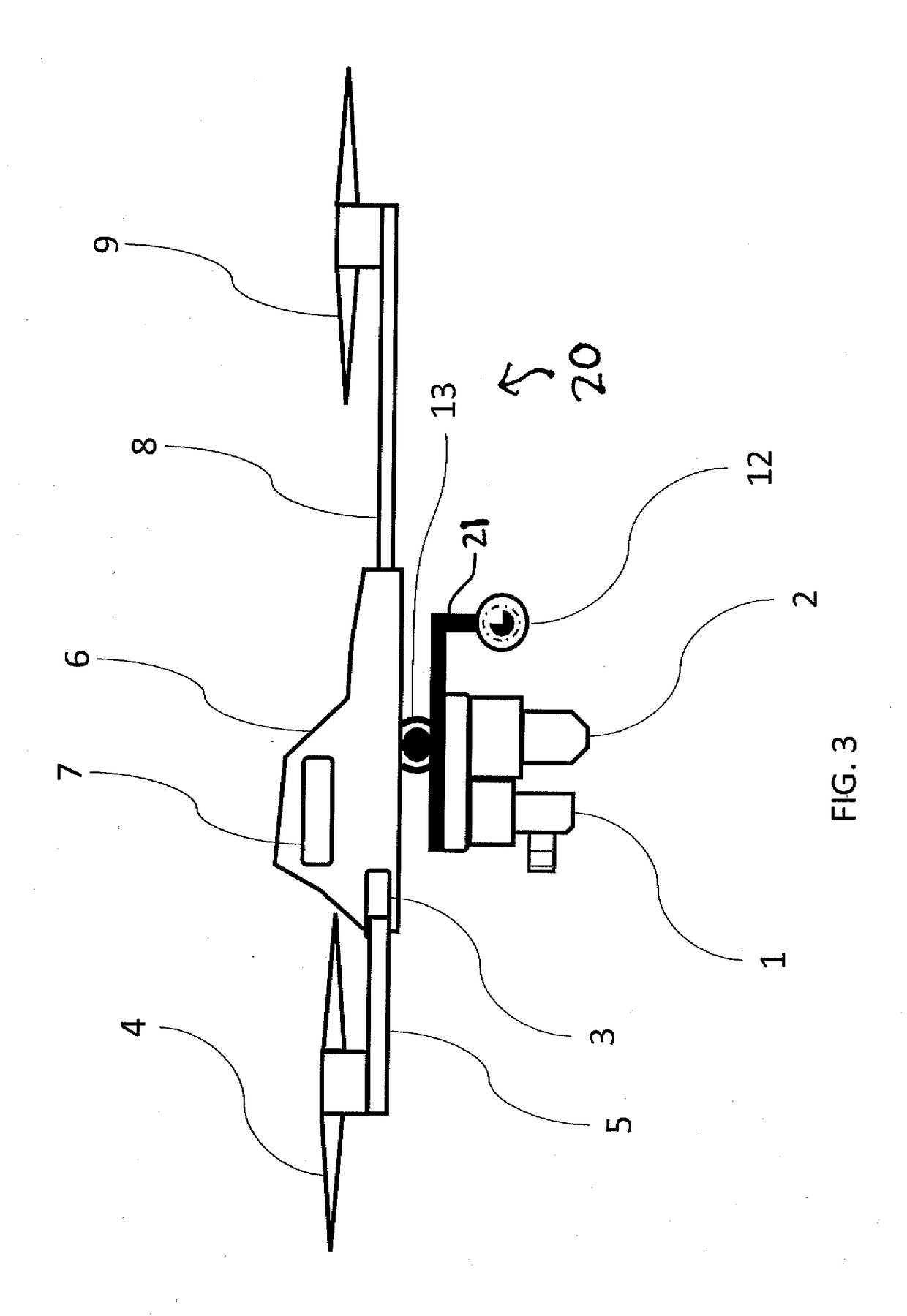
No prior GPR technique provides efficient, integrated surface+subsurface inspections from a compact, airborne Unmanned Aerial
System (UAS) or compact terrestrial platform.
Separate GPR and
LIDAR results can also be laboriously processed on site and manually mapped onto site surfaces as paint markings indicating the presence of subsurface features below, but this is presently difficult and
time consuming.
Prior to IS SM, combining GPR and
LIDAR required redundant procedures and analysis constrained to terrestrial data collection (limiting
automation potential).
Combined results are often difficult to analyze unless an expert is available.
Burns et al. fail to teach a device that provides integrated positioning information in GPS denied or GPS challenged environments and / or with irregular data sampling due to position under-sampling and interpolation requirements.
Burns et al. also fail to teach a device free from the need for complex mechanical wheel encoders that are inherently terrestrial and must maintain constant contact with the ground to function.
Finally, Burns et al. fail to teach a device intended for
virtual reality or
mixed reality applications and end users, including the lack of integrated surface and subsurface information.
Rodgers et al. fail to teach a device that provides subsurface sensing information to the
end user.
Rodgers et al. fail to teach a three-dimensional representation of site information, as said information is projected and painted onto two-dimensional site surfaces.
Ralston fails to teach real time positioning within accuracy required for
engineering applications.
Knierim fails to teach practical GPR data collection capabilities due to data sampling issues, including Equivalent Time (ET) measurement time
delay requirements to achieve useful
signal to
noise ratios.
Knierim also fails to teach capabilities to make results compatible with
augmented reality or mixed reality display of subsurface measurements.
Knierim fails to teach positioning measurement results within accuracy required for engineering applications.
Lewis et al, fail to teach location and orientation determination within engineering accuracy.
Lewis et al. fail to teach subsurface GPR data collection for
subsurface imaging and correlation with surface data.
Lewis et al. fail to teach compatibility with
augmented reality and mixed reality display of subsurface results.
Newcombe fails to teach efficient LIDAR sensing to map surface features and determine the position and orientation of the sensor apparatus.
Newcombe fails to teach
augmented reality and mixed reality display of subsurface results.
Newcombe fails to teach methods to provide engineering accurate position and orientation information.
Chang et al. fail to teach 3D LIDAR range imaging in three dimensions, as 3D LIDAR range image data are not collected (only conventional 2D images are collected).
Also, survey accurate positioning is not enabled.
In addition, Chang et al. fail to teach correlation of surface information with subsurface information, as no GPR data is made available or utilized.
Chau fails to teach 3D LIDAR range imaging, as LIDAR range image data are not collected (only conventional 2D images are collected).
Chau also fails to teach correlation of surface information with subsurface information, as no subsurface data (such as GPR data) is made available or utilized.
Abovitz et al. fail to teach 3D LIDAR range imaging, as LIDAR range image data are not collected.
Abovitz et al. fail to reliably provide surface or subsurface information with engineering accuracy (corresponding to engineering accuracy of the position and orientation of the data collection apparatus).
Abovitz et al. also fail to teach correlation of surface information with subsurface information, as no GPR data is made available or utilized.
Albert et al. fail to teach application of retroreflective electrophoretic displays and materials applications as a means to develop three-dimensional, dynamic targets for LIDAR and other imaging devices to detect and locate.
Further, Albert et al. fail to teach application of electrophoretic displays and materials applications as a means to symbolically
display device time (down to hundredths of a second or better) for the purpose of
synchronizing data collected by multiple devices.
Anderson et al. fail to teach dynamic retroreflective display technology to synchronize timing between sensing devices using a dynamic, retroreflective
clock image (utilizing retroreflective and electrophoretic display mapped onto a target).

