Method for Liquid Air Energy Storage with Semi-Closed CO2 Bottoming Cycle

a liquid air energy storage and bottoming cycle technology, applied in the direction of engine fuction, engine working fluid, lighting and heating apparatus, etc., can solve the problems of increasing the charging power and the required volume of the liquid air tank at the laes facility, and producing liquid air during off-peak hours is an energy-intensive process, so as to achieve the effect of increasing the pressure of liquid air

Active Publication Date: 2019-03-07
SINATOV STANISLAV
View PDF0 Cites 5 Cited by
  • Summary
  • Abstract
  • Description
  • Claims
  • Application Information

AI Technical Summary

Benefits of technology

[0017]Finally, in one or more embodiments, an amount of the liquid CO2 mixed with the re-gasified air may be increased through enhancement in pressure of liquid air produced and stored during LAES charge.

Problems solved by technology

However, producing a liquid air during off-peak hours is an energy intensive process and many technical solutions have been proposed to reduce the energy consumption during LAES charge, increase the energy release during LAES discharge and in this manner to improve the LAES round-trip efficiency.
The latter method seems to be the least substantiated by reason of excessively high specific air consumption typical for the gas turbine prime mover.
This air consumption exceeds that typical for the comparable in power reciprocating internal combustion engine by a factor 2-3, resulting in the attendant increase in charging power and a required volume of liquid air tank at the LAES facility.
However, even without any cryogenic exhaust treatment, the principles built into design and operation of any LAES facility already in themselves provide a very low level of CO2 emissions in engine exhaust, which is, for example, a half of upper limit on carbon emissions from the large stationary CC gas turbine power plants set up by the new U.S. Carbon Pollution Standard in 2015.
This circumstance weakens a motivation of the end-users on harnessing the proposed method for cleaning the LAES facility exhaust.
In addition, despite the general public concern by the problems of global warming, at the present time there are not a substantial active world CO2 market and the much accessible ways for CO2 sequestration, This creates the problems for the marketing the CO2 produced.

Method used


Image

  • Method for Liquid Air Energy Storage with Semi-Closed CO2 Bottoming Cycle

Examples


Embodiment Construction

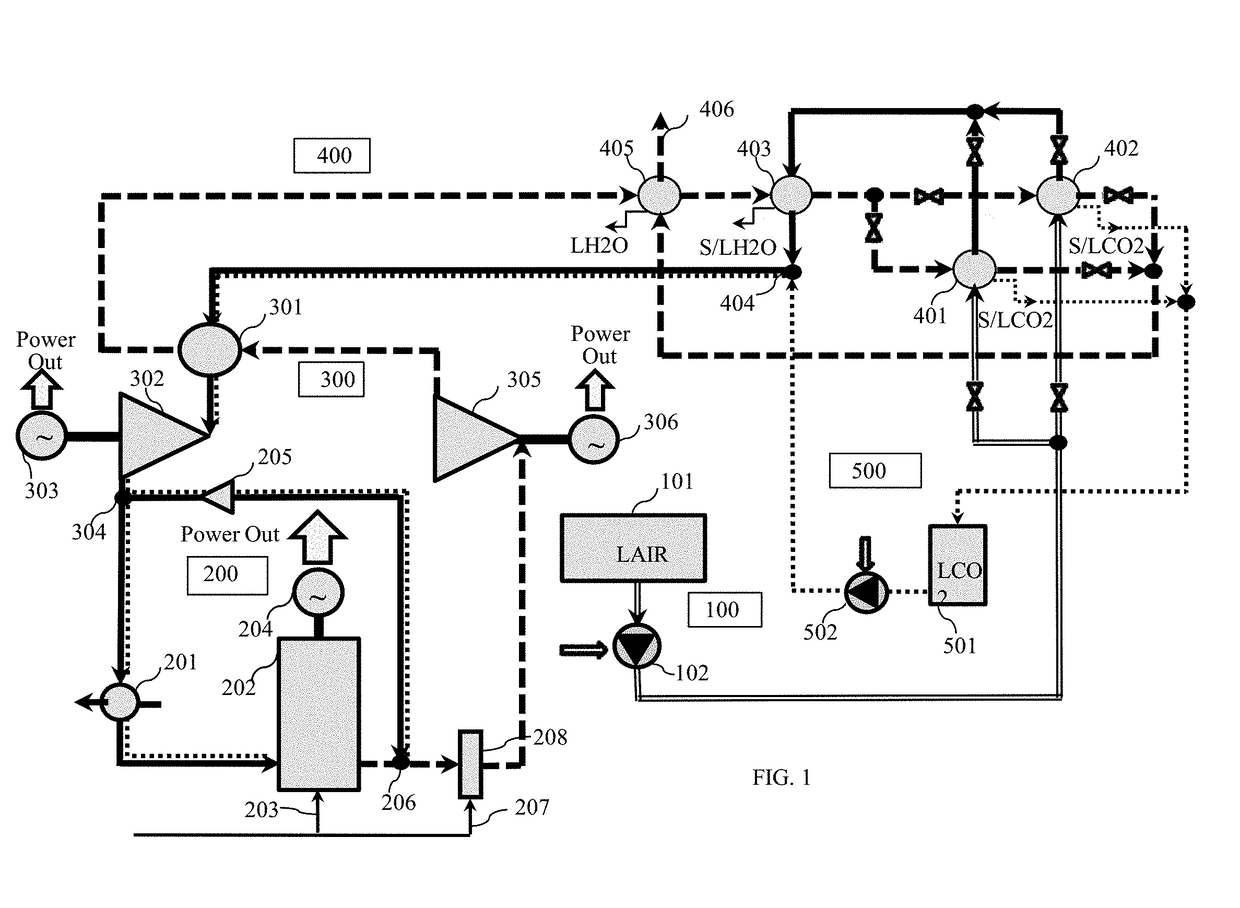
[0020]The practical realization of the invented method for Liquid Air Energy Storage (LAES) with semi-closed CO2 bottoming cycle may be performed through the integration between the liquefier of LAES facility, fueled supercharged reciprocating internal combustion engine (ICE) with associated turbo-expanders package and system for exhaust gas treatment including cryogenic capture of a part of CO2 emissions from facility exhaust with recovery of the captured CO2 emissions in the said bottoming cycle. Such the integration makes possible to maximize power output and round-trip efficiency of the energy storage and to significantly suppress the formation of the thermal NOx emissions. The LAES operation includes the modes of its charge and discharge. The charge operation mode is identical to that described in the published U.S. Patent Application No. 2018 / 0221807 and therefore its detailed explanation is not needed here.

[0021]FIG. 1 shows schematically the first embodiment of the power blo...


PUM


Abstract

A proposed method provides a highly efficient fueled power output augmentation of the liquid air energy storage (LAES) through its integration with the semi-closed CO2 bottoming cycle. It combines the production of liquid air in air liquefier during LAES charge using excessive power from the grid and an effective recovery of stored air for production of on-demand power in the fueled supercharged reciprocating internal combustion engine (ICE) and associated expanders of the power block during LAES discharge. A cold thermal energy of liquid air being re-gasified is recovered for cryogenic capturing most of CO2 emissions from the facility exhaust with following use of the captured CO2 in the semi-closed bottoming cycle, resulting in enhancement of total LAES facility discharge power output and suppressing the thermal NOx formation in the ICE.

Description

CROSS-REFERENCE TO RELATED APPLICATIONS[0001]This application claims the benefits of U.S. Provisional Patent Application No. 62 / 554,053 titled “Method for Liquid Air Energy Storage with semi-closed CO2 bottoming cycle” and filed on Sep. 5, 2017.STATEMENT REGARDING FEDERALLY SPONSORED RESEARCH OR DEVELOPMENT[0002]Not ApplicableREFERENCE TO SEQUENCE LISTING, A TABLE, OR A COMPUTER PROGRAM LISTING COMPACT DISK APPENDIX[0003]Not ApplicableFIELD OF INVENTION[0004]The present invention relates to the field of energy conversion technique, and more specifically to the methods enabling an improvement in the technologies intended for conversion and storage of excessive energy in the electric grids. More particularly, the present invention relates to the methods making possible to provide a highly efficient fueled power augmentation of the liquid air energy storage simultaneously with a drastically reduced level of NOx and CO2 emissions in its exhaust.BACKGROUND OF THE INVENTION[0005]In modern...

Claims


Application Information

Patent Timeline
Patent Type & Authority Applications(United States)
IPC IPC(8): F01K27/00F25J1/00F25J1/02F02C6/16F01K13/00
CPCF01K27/00F25J1/0012F25J1/0027F25J1/0035F25J1/0042F25J1/0242F02C6/16F01K13/00F25J2260/30F25J2260/80B01D53/002B01D53/265B01D2257/504B01D2257/80B01D2258/0283F01K23/065F01K23/10F01K23/103F01K25/103F02C1/08F05D2210/10F05D2220/62F05D2260/10Y02E20/18Y02E20/32Y02E60/16F17C9/04
Inventor SINATOV, STANISLAV
Owner SINATOV STANISLAV
Why Eureka
Try Eureka