
Protective caps of tips for surgical laser fibers

Active Publication Date: 2019-03-21
OPTICAL INTEGRITY INC
View PDF0 Cites 3 Cited by
  • Summary
  • Abstract
  • Description
  • Claims
  • Application Information

AI Technical Summary

Benefits of technology

This patent aims to provide a cost-effective solution to protect an endoscope from damage caused by inserting a fiber or fiber assembly. The solution also limits erosion of the fiber tip and protects the endoscope from damage. Additionally, it minimizes scope damage during lasing procedures.

Problems solved by technology

One problem with current optical fibers is that when the fibers are introduced into an endoscope, the fibers can score or puncture the soft working channel of the endoscope.
The damage to the endoscope's working channel can be very expensive or even harmful to the patient.
However, this solution only provides protection during initial insertion of the fiber into the scope, before the fiber is used for lasing.
In addition, the process of forming the ball tip necessitates removal of protective coatings on the fiber, and exposes the fiber to moisture during ball formation.
The moisture causes static fatigue and weakens the fiber, leaving it subject to breakage inside the scope, as previously reported in the FDA MAUDE REPORTS.
Although a particular problem in the context of ball tips, conventional planar fiber end faces may also be subject to erosion.
However, while the hollow metal tip serves as a spacer to prevent the fiber tip from touching a stone, thereby reducing erosion, the metal tip only exacerbates the problem of damage to the working channel of the scope, since the metal tip will increase the risk of scoring or puncturing the working channel, Furthermore, the use of a hard or metal tip can increase the risk of damaging delicate tissue surfaces such as the mucosa found in the ureter, either by physically damaging the tissue surfaces or by excessive heat due to absorption of treatment radiation by the metal tip.
However, scissors or other blades can still leave jagged edges that can damage the endoscope or introducer into which the fiber is inserted, and furthermore leaves the fiber vulnerable to peeling of the buffer, as illustrated in FIGS. 8A to 8C, in which an eroded fiber 41 having a buffer 42 and cladding 48 is cut with scissors along a cut line 49 to obtain a freshly cut fiber 47 (FIG. 8B), but nevertheless is vulnerable to erosion and buffer peeling after lasing, as shown in FIG. 8C.
However, they are not suitable for urological or other applications that involve end firing lasers subject to erosion of the fiber end-face.
To the contrary, fiber tip erosion continues to be a serious problem, with effects that cannot be eliminated by spherical ball tips, hollow steel tips, or even frequent re-cleaving of the fiber tip during a treatment procedure.
These effects include limitations on treatment energy and fiber diameter, which in turn result in prolonged treatment time and enhanced retro-repulsion between the laser and the stone or other object or tissue being targeted by the laser.
Still further, the use of unprotected fiber tips has led to previously unappreciated or unaddressed problems resulting from flashes that occur upon contact between the fiber tip and stones or other tissues.
One such problem is the problem of saturation of the endoscope camera as a result of the flash-induced influx of light energy, which can temporarily cause the loss of vision of the treatment site.
However, an even more potentially serious problem is the problem of charring caused by the energy influx, which can create weaknesses in the fiber at points located a significant distance away from the fiber tip.
When a flash occurs, a white flash enters the fiber and is absorbed by the dyed portion of the buffer, whereupon charring can occur within seconds, causing a weak spot in the buffer that is not easily visible through the scope but that can lead to sudden and unexpected fiber breakage.
The charring effect, like the saturation effect, can be alleviated by preventing contact between the fiber tip and the tissue being treated, but such contact prevention using a bare fiber tip is difficult or impossible to achieve in practice, or is contrary to common surgical techniques.

Method used


Image

  • Protective caps of tips for surgical laser fibers
  • Protective caps of tips for surgical laser fibers
  • Protective caps of tips for surgical laser fibers

Examples


Embodiment Construction

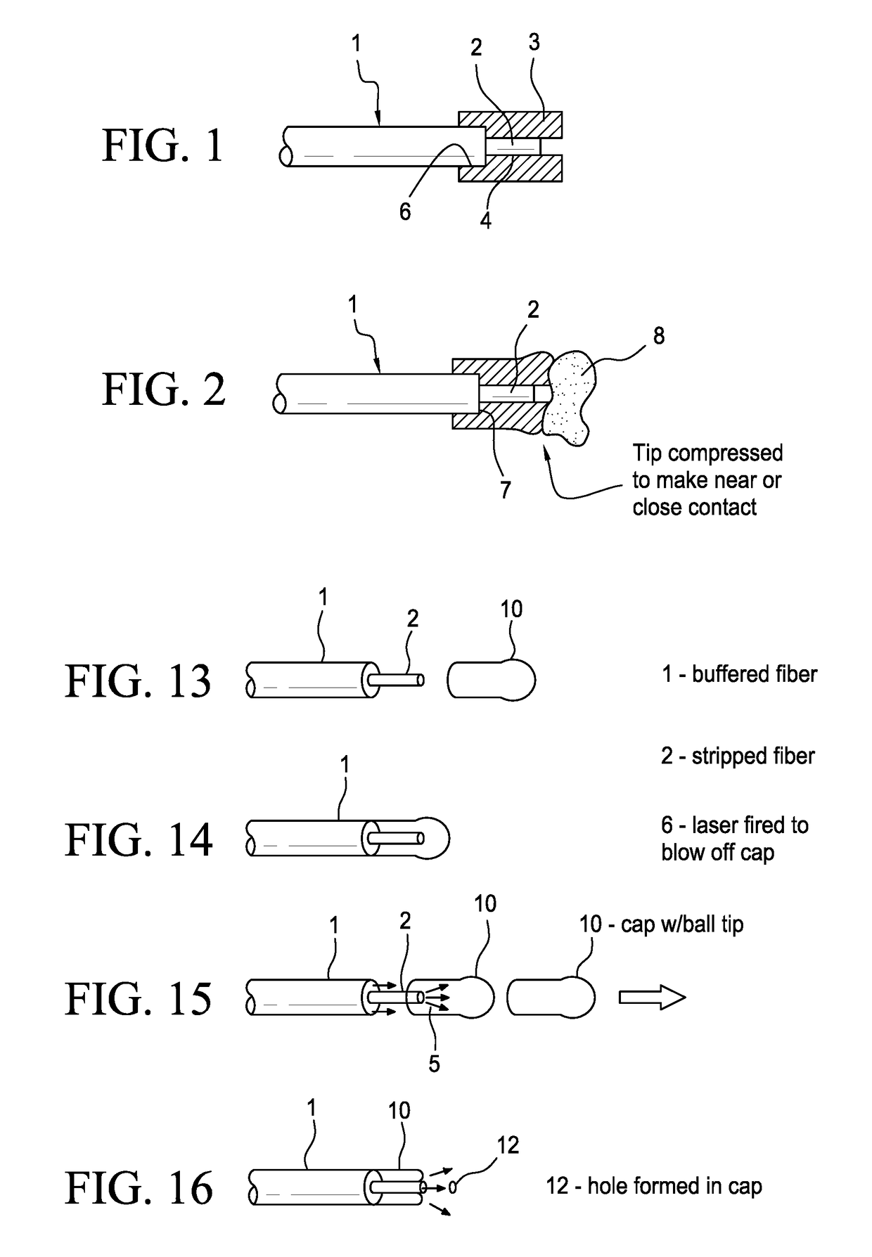
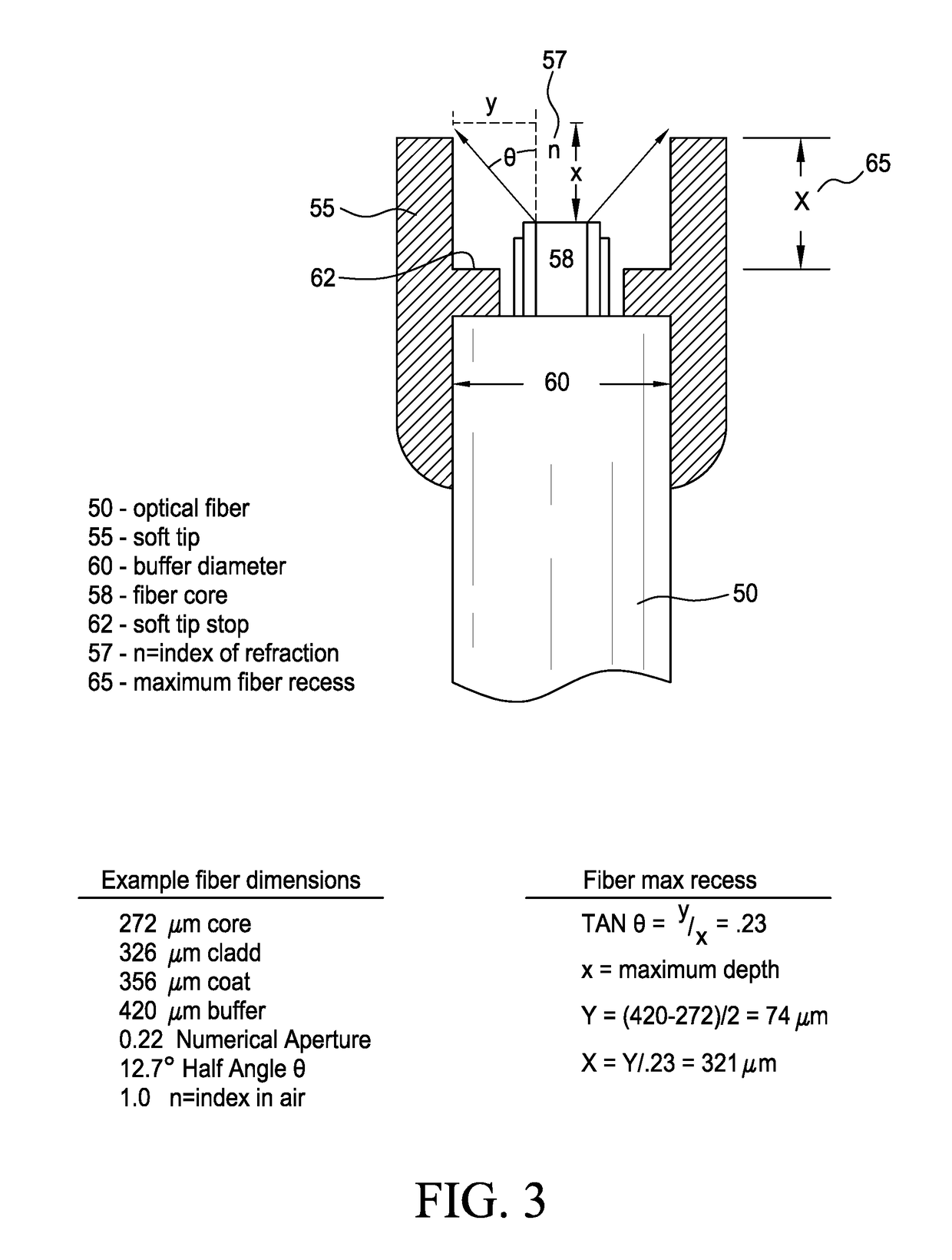
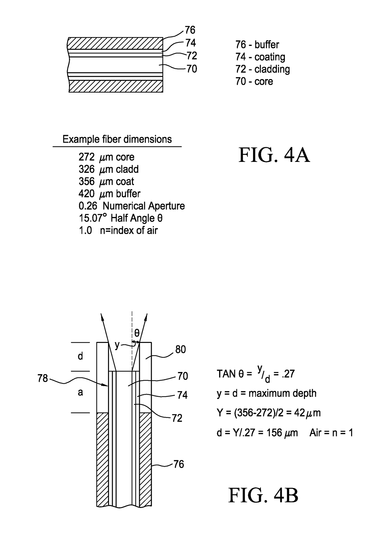
[0062]As shown in FIGS. 1-3, the distal end of an optical fiber 1 used in laser surgery applications is surrounded by a soft tip or protective sleeve structure 3 (hereinafter referred to as a “soft tip”) that protects an endoscope from damage as the optical fiber is inserted into the scope prior to lasing, and that also reduces erosion of the end face of the fiber during lasing. The fiber 1 is, by way of example, an end-firing fiber of the type used in urological stone removal applications, although the soft tip or protective sleeve structure of this embodiment of the invention is not necessarily limited to stone removal or urological applications, or to end-firing lasers, but rather may be used in connection with any optical fiber through which radiation or laser energy is supplied to tissues or other objects in the treatment area that may come into contact with an end section or face of the fiber.

[0063]The soft tip 3 has a generally cylindrical exterior surface and a central bore....


PUM


Abstract

A distal end of an optical fiber may be protected by a variety of alternative protective caps, tips, and / or sleeves. In one example, a generally cylindrical soft tip is arranged to fit over the end of the fiber, and to compress in an axial direction when pressed against a stone to allow a recessed tip of the fiber to contact the stone or to be maintain a minimum spacing between the fiber tip and the stone and thereby limit erosion of the fiber tip.

Description

[0001]This application claims the benefit of provisional U.S. Patent Appl. Ser. Nos. 62 / 332,285, filed May 5, 2016; 62 / 336,888, filed May 16, 2016; 62 / 399,677, filed Sep. 26, 2016; and 62 / 465,407, filed Mar. 1, 2017, each of which is incorporated by reference herein.BACKGROUND OF THE INVENTION1. Field of the Invention[0002]The invention relates to protective caps or tips that are placed over a surgical laser optical fiber to protect the working channel of an endoscope during insertion of the optical fiber through the endoscope in preparation for a treatment procedure.[0003]The invention is especially applicable to the treatment procedure known as lithotripsy, in which laser energy is applied to a hard piece of material known as a stone, which can obstruct a patient's kidney or urinary tract. The laser radiation destroys or breaks up the stone so that it can pass more easily through and out of the patient's kidney, bladder, and / or ureter. The stone may be referred to herein by the te...

Claims


Application Information

Patent Timeline
IPC IPC(8): A61B18/26A61B1/00
CPCA61B18/26A61B1/00137A61B1/0008A61B2018/00511A61B2018/00625A61B18/22A61B1/018G02B6/44G02B6/4415G02B6/443G02B6/4479G02B6/4486
Inventor BROWN, JOE D.MALPHURS, DANIELKLYMAS, HOWARD S.
Owner OPTICAL INTEGRITY INC
Learn More