Turbomachine with Alternatingly Spaced Turbine Rotor Blades

a technology of alternating space and turbine rotor blades, which is applied in the field of turbomachines, can solve the problems of insufficient electrical power supply for auxiliary generators and inconvenient configuration of electric fans,

Active Publication Date: 2019-03-21
GENERAL ELECTRIC CO
View PDF0 Cites 28 Cited by
  • Summary
  • Abstract
  • Description
  • Claims
  • Application Information

AI Technical Summary

Benefits of technology

The patent text describes a way to increase the speed of an electric machine's rotor compared to its connection member. This is achieved by using a gearbox that allows for a high gear ratio. The technical effect of this is that it helps to improve the performance and efficiency of the electric machine.

Problems solved by technology

However, several problems may arise with such a configuration relating to unwanted vibrations, clearance issues between the first and second pluralities of rotor blades, etc.
However, inclusion of a sufficient amount of energy storage devices with the propulsion system to power the electric fan may be space and weight prohibitive.
However, these auxiliary generators are not configured to provide a sufficient amount of electrical power to adequately drive the electric fan.

Method used


Image

  • Turbomachine with Alternatingly Spaced Turbine Rotor Blades
  • Turbomachine with Alternatingly Spaced Turbine Rotor Blades
  • Turbomachine with Alternatingly Spaced Turbine Rotor Blades

Examples


Embodiment Construction

[0054]Reference will now be made in detail to present embodiments of the invention, one or more examples of which are illustrated in the accompanying drawings. The detailed description uses numerical and letter designations to refer to features in the drawings. Like or similar designations in the drawings and description have been used to refer to like or similar parts of the invention.

[0055]As used herein, the terms “first”, “second”, and “third” may be used interchangeably to distinguish one component from another and are not intended to signify location or importance of the individual components.

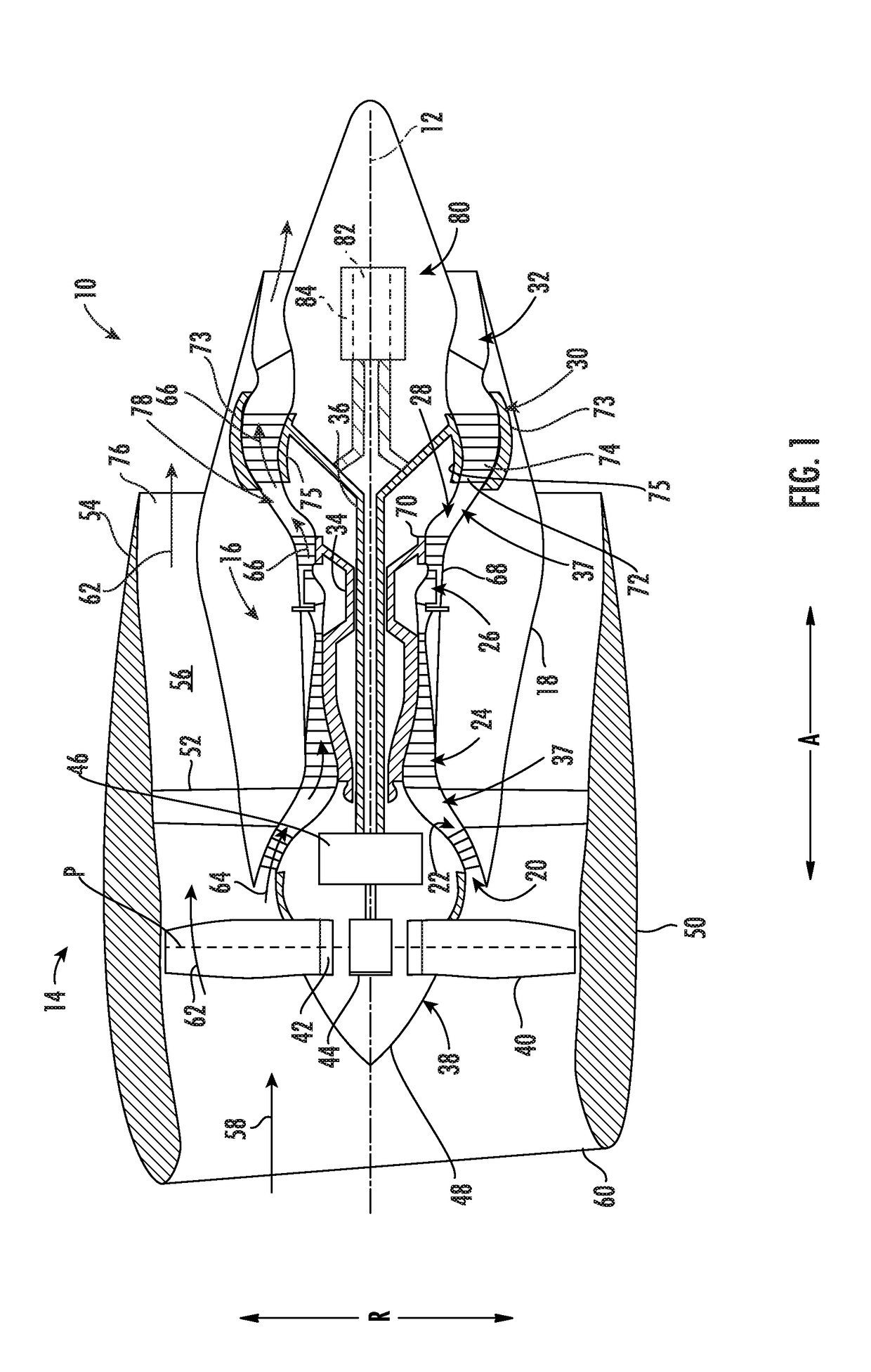
[0056]The terms “forward” and “aft” refer to relative positions within a gas turbine engine or vehicle, and refer to the normal operational attitude of the gas turbine engine or vehicle. For example, with regard to a gas turbine engine, forward refers to a position closer to an engine inlet and aft refers to a position closer to an engine nozzle or exhaust.

[0057]The terms “upstream” and “...


PUM


Abstract

An engine assembly includes an engine including a component and defining an opening and an interior, the component including a first side and an opposite second side, the second side positioned within the interior of the engine. The engine assembly also includes an inspection tool having a first member including at least one of a receiver or a transmitter and directed at the first side of the component. The inspection tool also includes a second member including the other of the receiver or the transmitter and positioned at least partially within the interior of the engine and directed at the second side of the component to communicate a signal with the first member through the component, the second member being a robotic arm extending through the opening of the engine.

Description

CROSS-REFERENCE TO RELATED APPLICATIONS[0001]This application is a non-provisional application claiming the benefit of priority under 35 U.S.C. § 119(e) to U.S. Provisional Application No. 62 / 548,666 filed Aug. 22, 2017, which is hereby incorporated by reference in its entirety.FIELD[0002]The present subject matter relates generally to a turbomachine, and more particularly, to a turbine of a turbomachine having alternatingly spaced turbine rotor blades.BACKGROUND[0003]Typical aircraft propulsion systems include one or more gas turbine engines. For certain propulsion systems, the gas turbine engines generally include a fan and a core arranged in flow communication with one another. Additionally, the core of the gas turbine engine general includes, in serial flow order, a compressor section, a combustion section, a turbine section, and an exhaust section. In operation, air is provided from the fan to an inlet of the compressor section where one or more axial compressors progressively ...

Claims


Application Information

Patent Timeline
Patent Type & Authority Applications(United States)
IPC IPC(8): F01D15/10F02C7/32H02K7/18
CPCF01D15/10F02C7/32H02K7/1823F05D2220/323F05D2240/24F05D2260/40311F01D5/06F01D25/16F01D25/28F04D25/06F01D1/24F02K3/06F02C3/067F02C3/107F05D2220/76Y02T50/60F01D5/03
Inventor VAN DER MERWE, GERT JOHANNESZATORSKI, DAREK TOMASZ
Owner GENERAL ELECTRIC CO
Why Eureka
Try Eureka