
Microfluidic Device and Method for Isolation of Nucleic Acid

a microfluidic device and nucleic acid technology, applied in fluid controllers, laboratory glassware, chemistry apparatus and processes, etc., can solve the problems of time and cost investment, unable to detect tf-dna interactions, and no existing techniques, etc., to explore the comprehensive mapping of dna binding specificities of tf heterodimers or even larger complexes, and achieve cost-effective and time-saving effects

Inactive Publication Date: 2019-03-28
ECOLE POLYTECHNIQUE FEDERALE DE LAUSANNE (EPFL)
View PDF0 Cites 0 Cited by
  • Summary
  • Abstract
  • Description
  • Claims
  • Application Information

AI Technical Summary

Benefits of technology

The patent describes a special chip that helps to select specific parts of DNA based on their function. This chip can be controlled and used independently, making it easier to modify and use in different ways. The chip uses very small amounts of material to test and select for the best parts of DNA.

Problems solved by technology

At the same time, knowing which nucleic acid sequences in a genome are recognized by which proteins is crucial for understanding the gene regulatory networks underlying various biological processes and still remains an important challenge of fundamental science.
Despite the fact that several nucleic acid ligands have been identified through these technologies, the tedious procedure associated with screens as well as the cost of the screen remain a big issue for the massive integration of these standard technologies into any academic or drug developmental toolkit.
The characterization of the binding preferences of TFs and TF complexes remains an important challenge of molecular biology.
However, there are still a large number of factors for which the DNA binding sites are not yet known.
Moreover, none of the existing techniques, able to detect TF-DNA interactions, has been used to explore the comprehensive mapping of DNA binding specificities of TF heterodimers or even larger complexes.
This required specialized facilities, time and cost investments.
And still, devices fabricated of glass or silicon are mostly inutile for analyses of biological samples in solutions.
Silicon, in particular, is expensive, and opaque to visible and ultraviolet light, so cannot be used with conventional optical methods of sample detection.

Method used


Image

  • Microfluidic Device and Method for Isolation of Nucleic Acid
  • Microfluidic Device and Method for Isolation of Nucleic Acid
  • Microfluidic Device and Method for Isolation of Nucleic Acid

Examples


Embodiment Construction

MITOMI (Mechanically Induced Trapping of Molecular Interactions) Followed by HT (High Throughput) Sequencing (MITOMI-Seq)

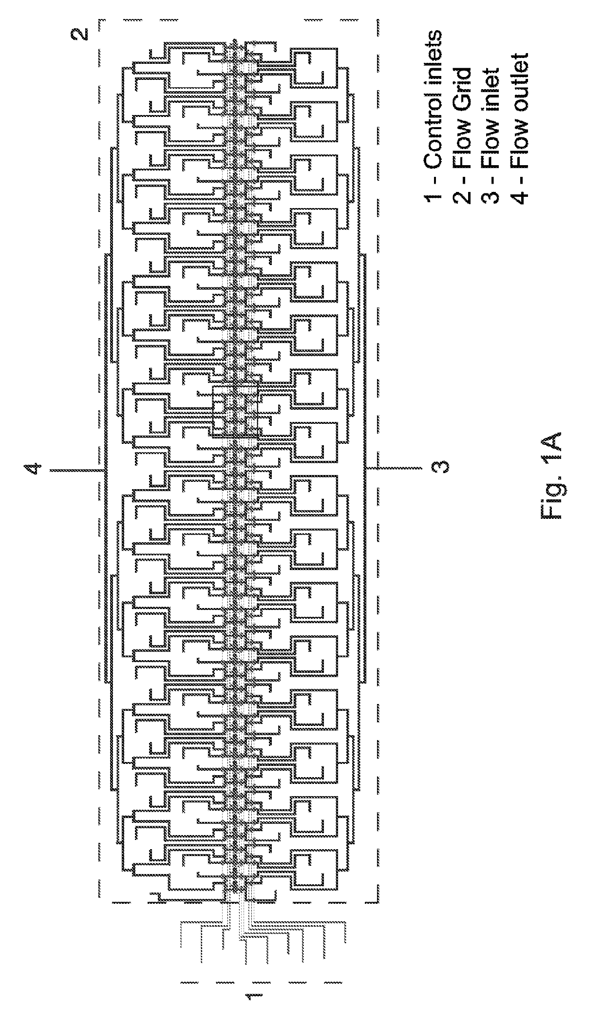
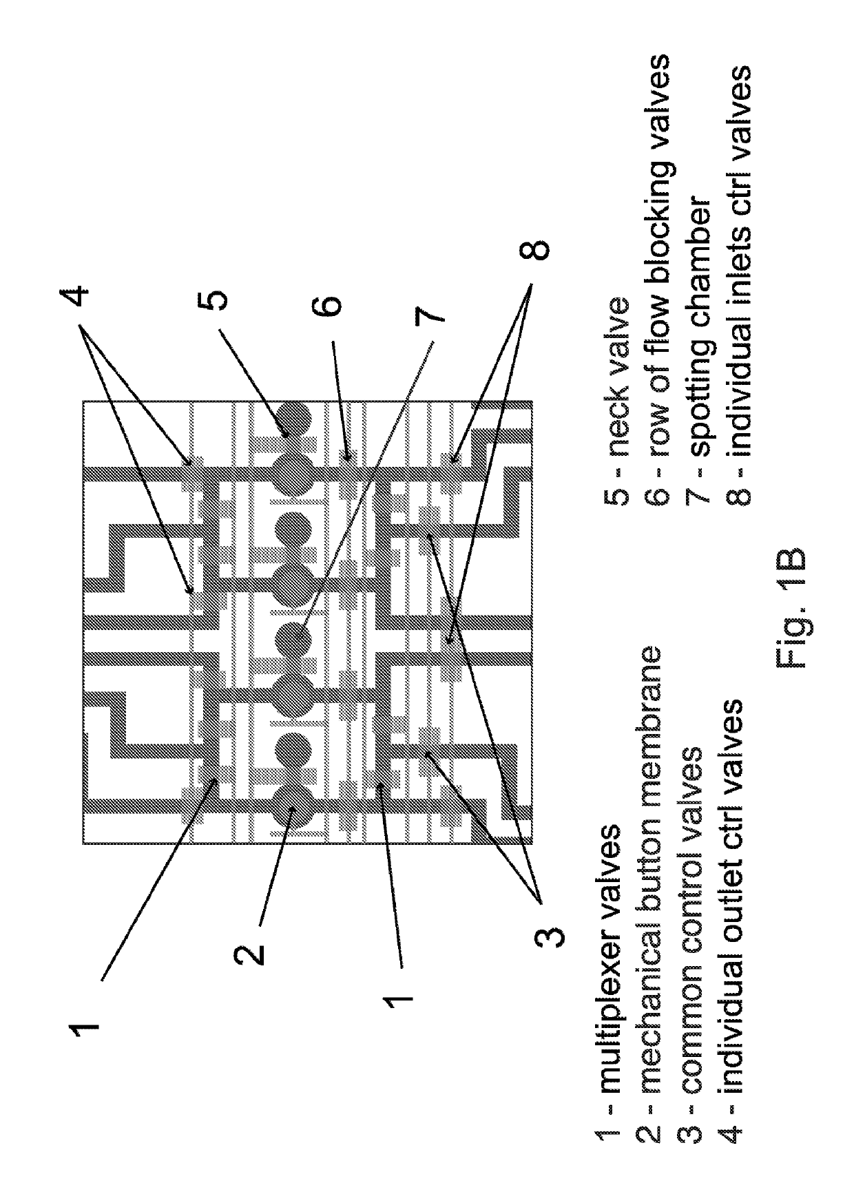
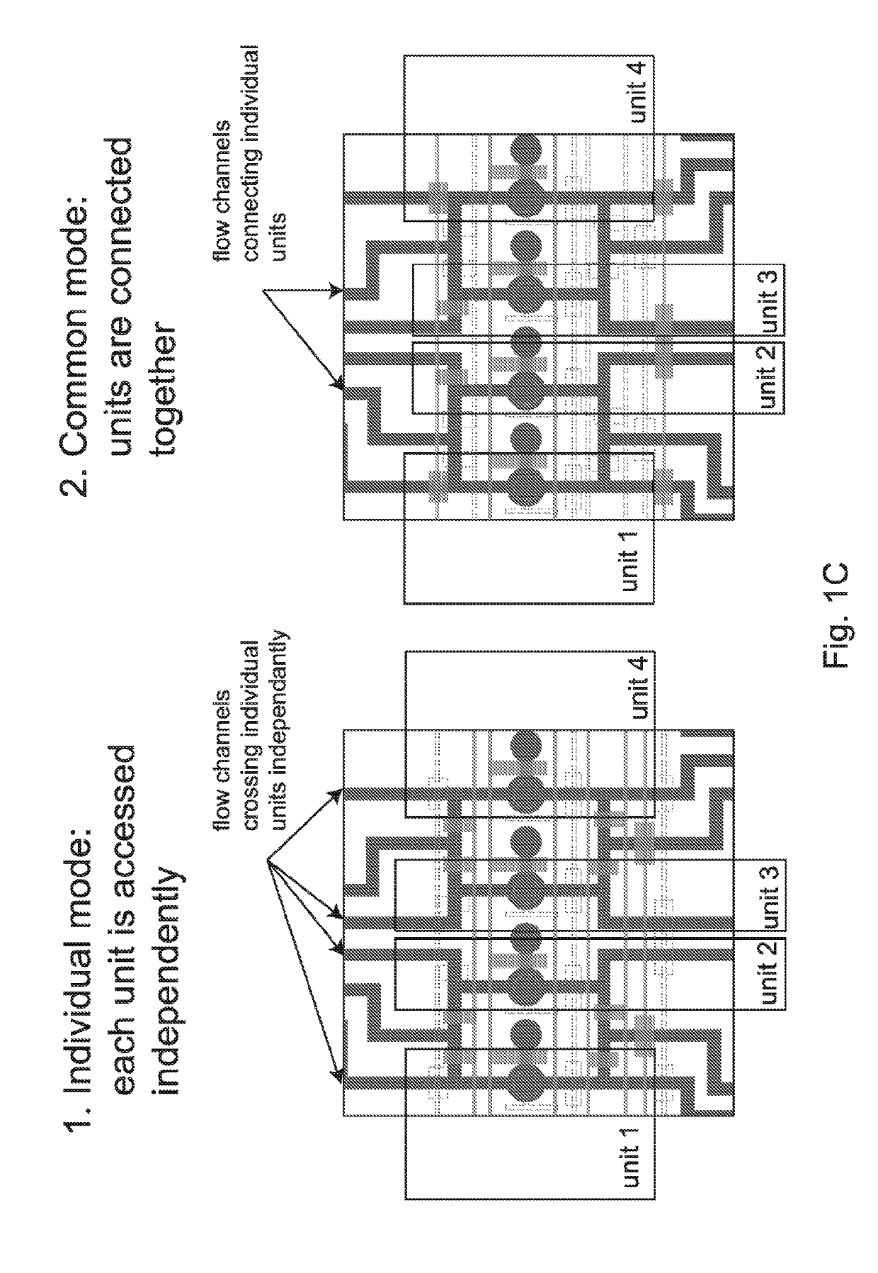
[0047]We first thought of using original MITOMI devices and an established protocol to perform an on-chip selection assay. Initial experiments revealed however that MITOMI devices suffered from a small and uncontrolled carry-over between neighboring units. Such a cross talk between units is typically not a problem for standard MITOMI applications that require a basic fluorescence-based read out. However, if one wants to recover bound DNA material from the device and subsequently analyze it with an extremely sensitive method like HT-sequencing, even small amounts of cross-contamination between samples may possibly skew data interpretation. Therefore there is a need for a device that can perform mechanically induced trapping of interactions but also allows a controlled isolation of individual units to be one of the key components of a successful on-chip selection pr...


PUM

PropertyMeasurementUnit
Timeaaaaaaaaaa
Interactionaaaaaaaaaa
Unit cellaaaaaaaaaa

Abstract

The present invention concerns a microfluidic device for mechanically induced trapping of molecular interactions comprising at least a first unit cell and a second unit cell, each unit cell comprising—a membrane chamber comprising a membrane, —a flow channel crossing the membrane chamber and having an inlet and an outlet, and the flow channel crossing the first unit cell being different from the flow channel crossing the second unit cell. Another object of the invention is a method for isolation of specifically bound nucleic acids to target molecules on said microfluidic device followed by its recovery and identification.

Description

CROSS-REFERENCE TO RELATED APPLICATIONS[0001]This application claims the benefit of international patent application PCT / IB2014 / 065418 filed Oct. 17, 2014 the entire contents of which are incorporated herein by reference.REFERENCE TO A SEQUENCE LISTING[0002]The instant application contains a Sequence Listing which has been submitted electronically in ASCII format and is hereby incorporated by reference in its entirety. The copy of the Sequence Listing, created on Aug. 21, 2018, is named P2826US00_SeqList_ST25.txt and is 6,661 bytes in size. This application contains a partial sequence list in Table 5.FIELD OF THE INVENTION[0003]The present invention generally relates to the identification of nucleic acids specifically bound to organic targets. More specifically the present invention relates to: 1) microfluidic devices which are capable of selective isolation and purification of nucleic acids specifically bound to protein targets; 2) method for preparation, on-chip processing and rec...

Claims


Application Information

Patent Timeline
IPC IPC(8): B01L3/00C12N15/115C40B60/02C40B60/12
CPCB01L3/502761C12N15/115C40B60/02C40B60/12B01L2300/0864B01L2300/0877B01L2400/0655B01L3/502738B01L2300/0867
Inventor ISAKOVA, ALINADEPLANCKE, BART
Owner ECOLE POLYTECHNIQUE FEDERALE DE LAUSANNE (EPFL)
Learn More