Boosted engine

a technology of boosted engine and boosted piston, which is applied in the direction of electric control, ignition automatic control, machines/engines, etc., can solve the problems of excessive combustion noise and engine performance that performs conventional combustion caused by compression ignition, and achieves the effect of avoiding the increase of unburned components and reducing soot generation

Active Publication Date: 2019-03-28
MAZDA MOTOR CORP
View PDF0 Cites 16 Cited by
  • Summary
  • Abstract
  • Description
  • Claims
  • Application Information

AI Technical Summary

Benefits of technology

[0038]That is, the end timing of the second injection is not retarded although the injection amount of the second injection is increased on the compression stroke, the time from the in

Problems solved by technology

Incidentally, the engine which performs the conventional combustion caused by compression ignition incurs a relatively loud combustion noise.
For example, if thi

Method used


Image

  • Boosted engine
  • Boosted engine
  • Boosted engine

Examples


Embodiment Construction

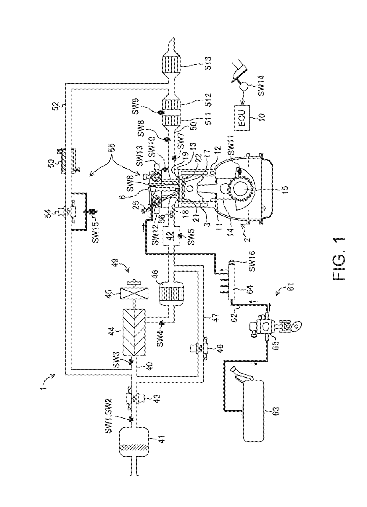
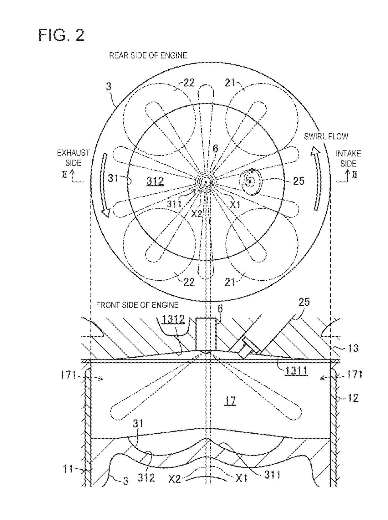
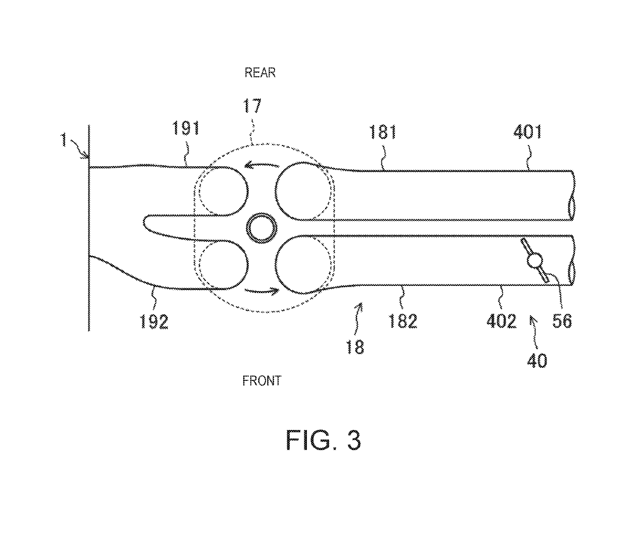
[0056]Hereinafter, one embodiment of a boosted engine is described in detail with reference to the accompanying drawings. FIG. 1 is a diagram illustrating a configuration of an engine 1. FIG. 2 is a view illustrating a structure of a combustion chamber 17, in which the upper part is a plan view of the combustion chamber 17 and the lower part is a cross-sectional view taken in a line II-II. FIG. 3 is a plan view illustrating structures of the combustion chamber 17 and an intake system. FIG. 4 is a block diagram illustrating a configuration of the control device for the engine. Note that in FIG. 1, an intake side is on the left side and an exhaust side is on the right side of the drawing sheet. Further in FIGS. 2 and 3, the intake side is on the right side and the exhaust side is on the left side of the drawing sheets.

[0057]The engine 1 is a four-stroke engine which is operated by the combustion chamber 17 repeating intake stroke, compression stroke, expansion stroke, and exhaust stro...


PUM


Abstract

A boosted engine is provided, which includes an engine body formed with a combustion chamber, a spark plug, a fuel injection valve, a booster, a boost controller, and a control unit including an operating range determining module and a compression end temperature estimating module. In a high load range, the fuel injection valve and the spark plug are controlled so that a mixture gas inside the combustion chamber starts combustion through flame propagation by ignition of the spark plug, and unburned mixture gas then combusts by compression ignition, and the boost controller is controlled to bring the booster into a boosting state. When a gas temperature inside the combustion chamber exceeds a given temperature at CTDC, the fuel injection valve is controlled so that a fuel injection end timing occurs on a compression stroke, and the spark plug is controlled so that the mixture gas is ignited after CTDC.

Description

TECHNICAL FIELD[0001]The present disclosure relates to a boosted engine.BACKGROUND OF THE DISCLOSURE[0002]JP4082292B discloses an engine in which a mixture gas inside a combustion chamber is combusted by compression ignition within a given operating range of the engine in which an engine load and an engine speed are low. In this engine, the mixture gas combusts by spark-ignition within an operating range in which the engine load is higher than the given operating range and an operating range in which the engine speed is higher than the given operating range. Further in this engine, also within the given operating range, a spark plug performs the spark-ignition near a top dead center of compression stroke to stimulate compression ignition of the mixture gas.[0003]JP5447435B discloses an engine in which the mixture gas inside a combustion chamber is combusted by compression ignition within a high load range of the engine. In this engine, within an operating range where an engine load ...

Claims


Application Information

Patent Timeline
IPC IPC(8): F02D41/00F02M26/22F02D13/02F02B37/16F02D41/40F02P5/04F02B23/10
CPCF02D41/0007F02D41/0052F02M26/22F02D13/023F02B37/16F02D41/0057F02D41/402F02P5/045F02B23/10F02D2200/022F02M2026/004F02B2037/162F02D2200/10F02B2023/108F02D13/0223F02D13/0276F02D15/00F02D35/025F02D41/0077F02D41/3017F02D41/401F02P5/1502F02D41/3041F02D41/0072F02D35/026F02D37/02F02B37/162F02P5/152Y02T10/12Y02T10/40F02D13/0261
Inventor INOUE, ATSUSHIARAKI, KEIJI
Owner MAZDA MOTOR CORP
Why Eureka
Try Eureka