
Electron stripper foils and particle accelerators having the same

Active Publication Date: 2019-04-11
GENERAL ELECTRIC CO
View PDF3 Cites 2 Cited by
  • Summary
  • Abstract
  • Description
  • Claims
  • Application Information

AI Technical Summary

Benefits of technology

The patent text describes a method for improving adhesion between a foil and a layer of conductive material. This is achieved by adding an intermediate layer between the foil and the conductive layer. This intermediate layer can be a carbon layer that is deposited using the same deposition process as the conductive layer. The technical effect of this method is that it provides a stronger bond between the foil and the conductive layer, which can improve the performance and reliability of the overall product.

Problems solved by technology

Target foils may also experience a corrosive and oxidizing environment due to contact with the starting material.
The elevated temperatures and pressures cause stress that renders the target foil vulnerable to rupture, melting, or other damage.
Target foils may also contaminate the target media when the ions from the target foil are absorbed by the starting material.
Stripper foils are also susceptible to degradation.
Over time, however, cyclical ion-beam exposures cause the graphite foils to wrinkle and / or fracture and become unsuitable for use.

Method used


Image

  • Electron stripper foils and particle accelerators having the same
  • Electron stripper foils and particle accelerators having the same
  • Electron stripper foils and particle accelerators having the same

Examples


Embodiment Construction

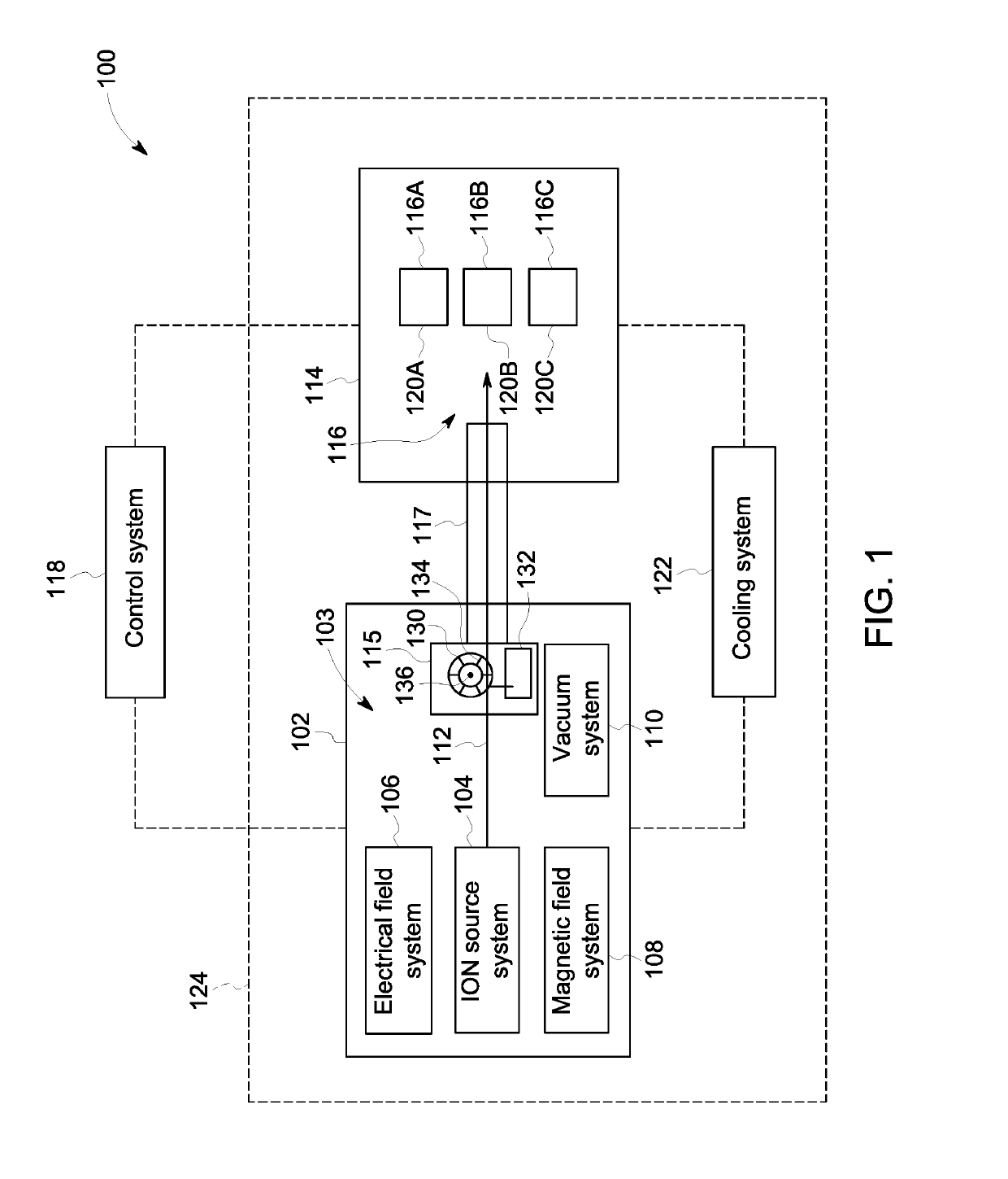
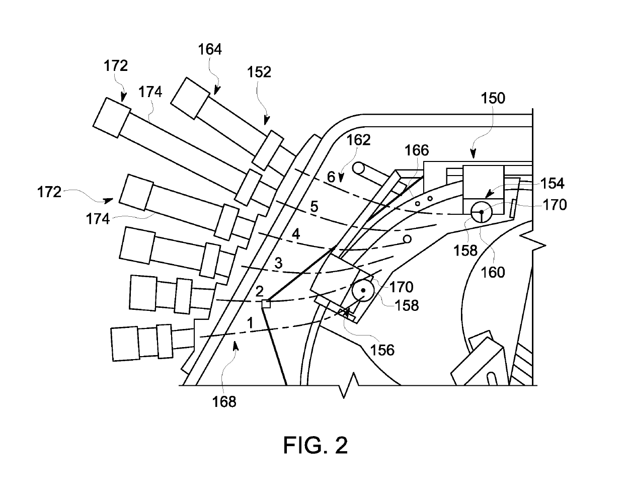
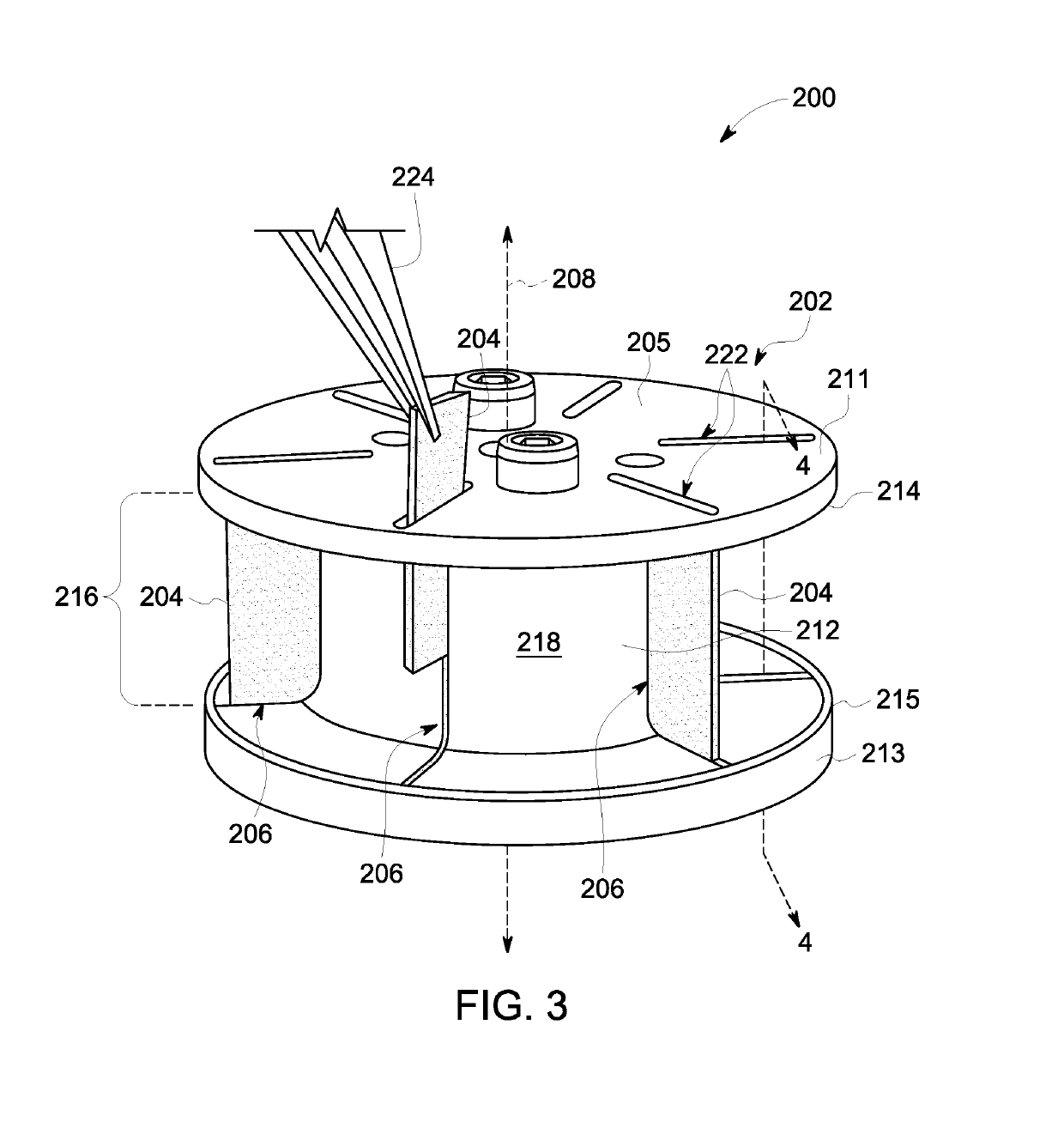
[0043]Embodiments described herein include particle accelerators, nuclide production systems, extraction devices, and stripper foils. The stripper foils may include two or more layers in which at least one layer is a backing layer and at least one layer is a conductive layer. In some embodiments, the backing layer is disposed between two conductive layers. The backing layer may provide designated mechanical properties of the stripper foil. The conductive layer provides a path to ground for a charge that may develop due to the accumulation of electrons. More specifically, the backing layer may be relatively insulative such that, without the conductive layer, a voltage build-up (e.g., up to several megavolts or more) along the stripper foil may reduce the lifetime of the stripper foil. In some embodiments, an additional layer is shaped to form a support section (or support frame) that may also provide designated mechanical properties.

[0044]At least one technical effect includes is a s...


PUM

PropertyMeasurementUnit
Thicknessaaaaaaaaaa
Thicknessaaaaaaaaaa
Temperatureaaaaaaaaaa

Abstract

System includes a particle accelerator configured to direct a particle beam of charged particles along a designated path. The system also includes an extraction device positioned downstream from the particle accelerator. The extraction device includes a stripper foil and a foil holder that holds the stripper foil. The foil holder is configured to position the stripper foil across the designated path of the particle beam such that the particle beam is incident thereon. The stripper foil is configured to remove electrons from the charged particles, wherein the stripper foil includes a backing layer and a conductive layer stacked with respect to one another. The backing layer includes synthetic diamond.

Description

BACKGROUND OF THE INVENTION[0001]The subject matter disclosed herein relates generally to particle accelerators, such as cyclotrons, and more particularly to particle accelerators that direct a beam of charged particles through a stripper foil that removes electrons from the charged particles.[0002]Particle accelerators can be used to generate radionuclides for medical therapy and imaging and also for research in medicine and physics. A cyclotron is a type of particle accelerator and may be one part of a larger nuclide production system. Like other particle accelerators, the cyclotron accelerates a beam of charged particles (e.g., H-ions) and directs the beam into a starting material to generate the isotopes. The cyclotron is a complex system that uses electrical and magnetic fields to accelerate and guide the charged particles along a predetermined orbit within an evacuated acceleration chamber. When the beam of charged particles reaches an outer portion of the orbit, the beam of c...

Claims


Application Information

Patent Timeline
IPC IPC(8): H05H7/10C23C16/26
CPCH05H2007/005C23C16/26H05H2007/125H05H7/10H05H7/001H05H13/005H05H7/12B32B2255/00
Inventor LIANG, YONGERIKSSON, TOMASNECULAES, VASILEDALAKOS, GEORGE THEODORE
Owner GENERAL ELECTRIC CO
Learn More