
Blade airfoil for an internally cooled turbine rotor blade, and method for producing the same

a turbine rotor blade and internal cooling technology, which is applied in the direction of engine fuction, leakage prevention, machines/engines, etc., can solve the problems of inlet on the inner side of the blade, component failure, undetected increase in cooling air consumption, etc., and achieves easy production, low tendency to failure, and greater reliability

Active Publication Date: 2019-04-25
SIEMENS ENERGY GLOBAL GMBH & CO KG
View PDF5 Cites 1 Cited by
  • Summary
  • Abstract
  • Description
  • Claims
  • Application Information

AI Technical Summary

Benefits of technology

The invention provides a blade airfoil for a turbine rotor blade that is designed to prevent contamination from particles in the cooling air. The method allows for easy production and increased reliability of these blade airfoils.

Problems solved by technology

This permits the formation of local corrosion phenomena and consequential damage, which in the worst case can lead to component failure.
It is a disadvantage that such hole inlets on the inner side of blades that are normally produced by precision casting methods can be produced not by boring but only by casting.
Owing to the use of precision casting methods, the cooling air holes however then have a relatively large diameter of at least approximately 2 mm, which undesirably increases the cooling air consumption.
Smaller diameters cannot be produced with sufficient accuracy.
There is then certainly only a very low risk of blockage, but the cooling air consumption is increased as a result of this.
By contrast, if the diameter thereof is reduced, for example in order to save cooling air, there is the risk of blockage, with the stated disadvantages.

Method used


Image

  • Blade airfoil for an internally cooled turbine rotor blade, and method for producing the same
  • Blade airfoil for an internally cooled turbine rotor blade, and method for producing the same
  • Blade airfoil for an internally cooled turbine rotor blade, and method for producing the same

Examples


Embodiment Construction

[0033]Below, identical technical features are denoted by the same reference designations in all of the figures. Furthermore, features of different exemplary embodiments may be combined with one another in any desired manner.

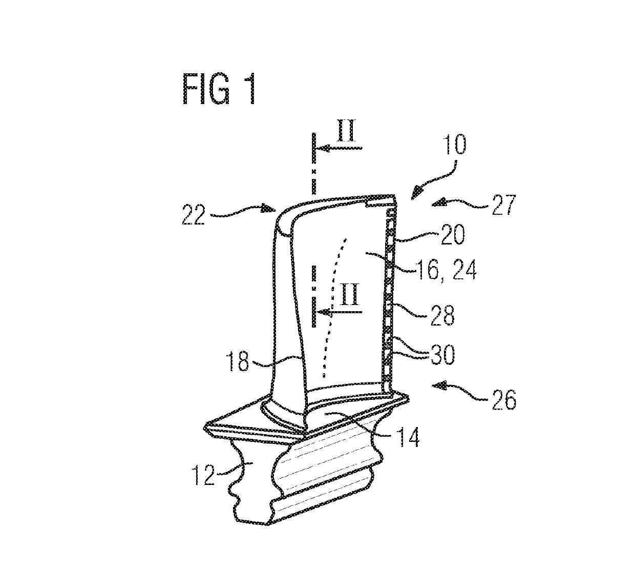
[0034]FIG. 1 shows a turbine blade 10 in a perspective illustration. The turbine blade 10 is, as per FIG. 1, designed as a rotor blade. It comprises a fir-tree-shaped blade root 12 and a platform 14 arranged thereon. The platform 14 is then adjoined by a blade airfoil 16, which is aerodynamically curved. It is not of importance for the invention whether or not the blade airfoil 16 is covered by a thermal protective layer. The blade airfoil 16 comprises a suction side wall 22 and a pressure side wall 24. In relation to a hot gas flowing around the blade airfoil 16, said walls extend from a leading edge 18 to a trailing edge 20. Along the trailing edge 20 there are provided a multiplicity of openings 28 for the discharge of coolant, which openings are separated fro...


PUM


Abstract

A blade airfoil for an internally cooled turbine rotor blade has suction-side and pressure-side side walls, which, extending from a common leading edge to a common trailing edge and in a span direction from a root-side end to a tip-side end, at least partially enclose a cavity. The tip-side end includes a tip wall which delimits the cavity at the tip side. At least one cooling hole for the discharge of cooling fluid that can be caused to flow in the interior is provided. In the cavity, at least one rib which extends from the tip wall in the direction of the root-side end projects from the inner surface, surrounding the rib, of the suction-side side wall and / or from the inner surface of the pressure-side side wall. An inflow-side end, in relation to the cooling fluid, of the at least one cooling hole opens out laterally in the respective rib.

Description

CROSS REFERENCE TO RELATED APPLICATIONS[0001]This application claims the benefit of European Application No. EP17197244 filed 19 Oct. 2017, incorporated by reference herein in its entirety.FIELD OF INVENTION[0002]The invention relates to a blade airfoil for an internally cooled turbine rotor blade. The invention also relates to a method for producing a blade airfoil.BACKGROUND OF INVENTION[0003]Turbine blades and the blade airfoils thereof have long been known from the extensive available prior art. In order that the turbine blades can permanently withstand the high temperatures that arise during operation, they are designed to be coolable. For this purpose, they have, in the interior, a cavity which can be flowed through by a coolant, normally cooling air, during operation. After flowing through the turbine blade and in particular through the blade airfoil thereof, the cooling air, which is heated as it flows through, is discharged into the working fluid of the gas turbine and mixe...

Claims


Application Information

Patent Timeline
IPC IPC(8): F01D5/18F01D9/04F01D25/12
CPCF01D5/186F01D9/041F01D25/12F05D2220/32F05D2240/12F05D2240/24F05D2260/202F05D2230/13F01D5/20F01D11/08F01D11/10F01D25/32
Inventor BUCHAL, TOBIAS
Owner SIEMENS ENERGY GLOBAL GMBH & CO KG
Features
  • Generate Ideas
  • Intellectual Property
  • Life Sciences
  • Materials
  • Tech Scout
  • Unparalleled Data Quality
  • Higher Quality Content
  • 60% Fewer Hallucinations
Learn More