Eureka AIR delivers breakthrough ideas for toughest innovation challenges, trusted by R&D personnel around the world.

Micro-localisation method and device for an imaging instrument and a measuring apparatus

Active Publication Date: 2019-04-25
HORIBA FRANCE SAS
View PDF0 Cites 9 Cited by
  • Summary
  • Abstract
  • Description
  • Claims
  • Application Information

AI Technical Summary

Benefits of technology

The micro-localisation device described in this patent allows for easy positioning of an imaging instrument over large areas of a sample and provides high-resolution images of cells or other elements within those areas. An image processing system can then analyze these images and determine the position and orientation of the cells or other elements with accuracy. The device uses a calibrated translation stage to accurately determine the position of a sample on the device. Overall, this device provides a way to localize measuring positions on a sample with sub-micrometric or nanometric accuracy and repeatability.

Problems solved by technology

Recurring problems are thus the re-localisation and co-localisation of measurements taken at different instants of time and / or with different measuring instruments.
However, the positioning system from document U.S. Pat. No. 7,630,628 does not make it possible to know the position of the measuring instrument with respect to the sample, i.e. to absolutely position the measuring instrument with respect to the sample.
This device requires an accurate and often laborious pre-positioning.
The localisation accuracy is limited by the pixel size and by the resolution of the imaging and image processing system.
In addition, the accuracy in angular orientation is limited, of around Δα˜10−2 radian.
This angular accuracy limitation induces positioning errors according to the distance between the alignment mark and the sample: at a distance d˜5 mm, the positioning error is proportional to d Δα˜50 microns, which is insufficient in applications on a microscopic scale.
The smaller the alignment mark is with respect to the size of the sample, the more laborious the pre-positioning is.
In addition, this system is limited to a restricted magnification range: if an alignment mark is suitable for a certain instrumental field of view, the instruments with a magnification which is too small cannot distinguish it, and the instruments with a magnification which is too large, cannot form a full image from it.
This device is consequently bulky, as the three alignment marks are arranged far from the sample.
Finally, this device can be sensitive to the thermal dilatation effects of the support which induce a positioning error and limit the accuracy of this device.
However, this alignment sight is not suitable for very different magnifications.
However, the accuracy of positioning and orientation of this multimodal and multiscale marker is fundamentally limited by the size of a pixel.

Method used


Image

  • Micro-localisation method and device for an imaging instrument and a measuring apparatus
  • Micro-localisation method and device for an imaging instrument and a measuring apparatus
  • Micro-localisation method and device for an imaging instrument and a measuring apparatus

Examples


Embodiment Construction

[0041]The following description regarding the appended drawings, given as non-limiting examples, will make understood what the invention consists of, and how it can be achieved.

[0042]In the appended drawings:

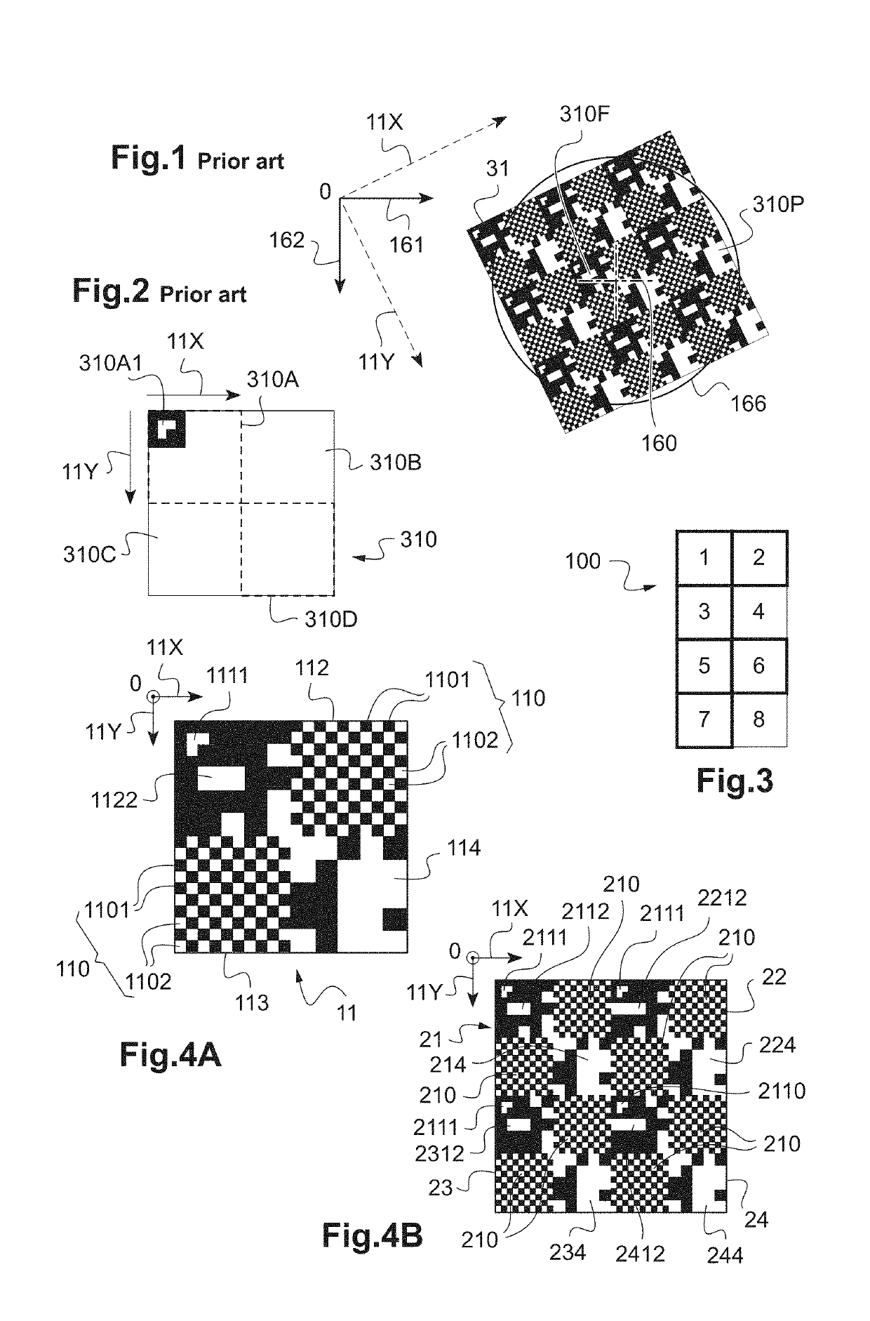
[0043]FIG. 1 represents an image of a part of a localisation sight according to the prior art;

[0044]FIG. 2 represents a schematic view of a localisation sight elementary cell illustrating a coding of identification, orientation and position patterns;

[0045]FIG. 3 schematically represents a macroscopic view of a micro-localisation device composed of a plurality of zones according to an embodiment;

[0046]FIG. 4A represents a schematic view of an example of a first zone of a micro-localisation device, this first zone including one single elementary cell;

[0047]FIG. 4B represents a schematic view of an example of a second zone of a micro-localisation device, this second zone including a tiling of four elementary cells;

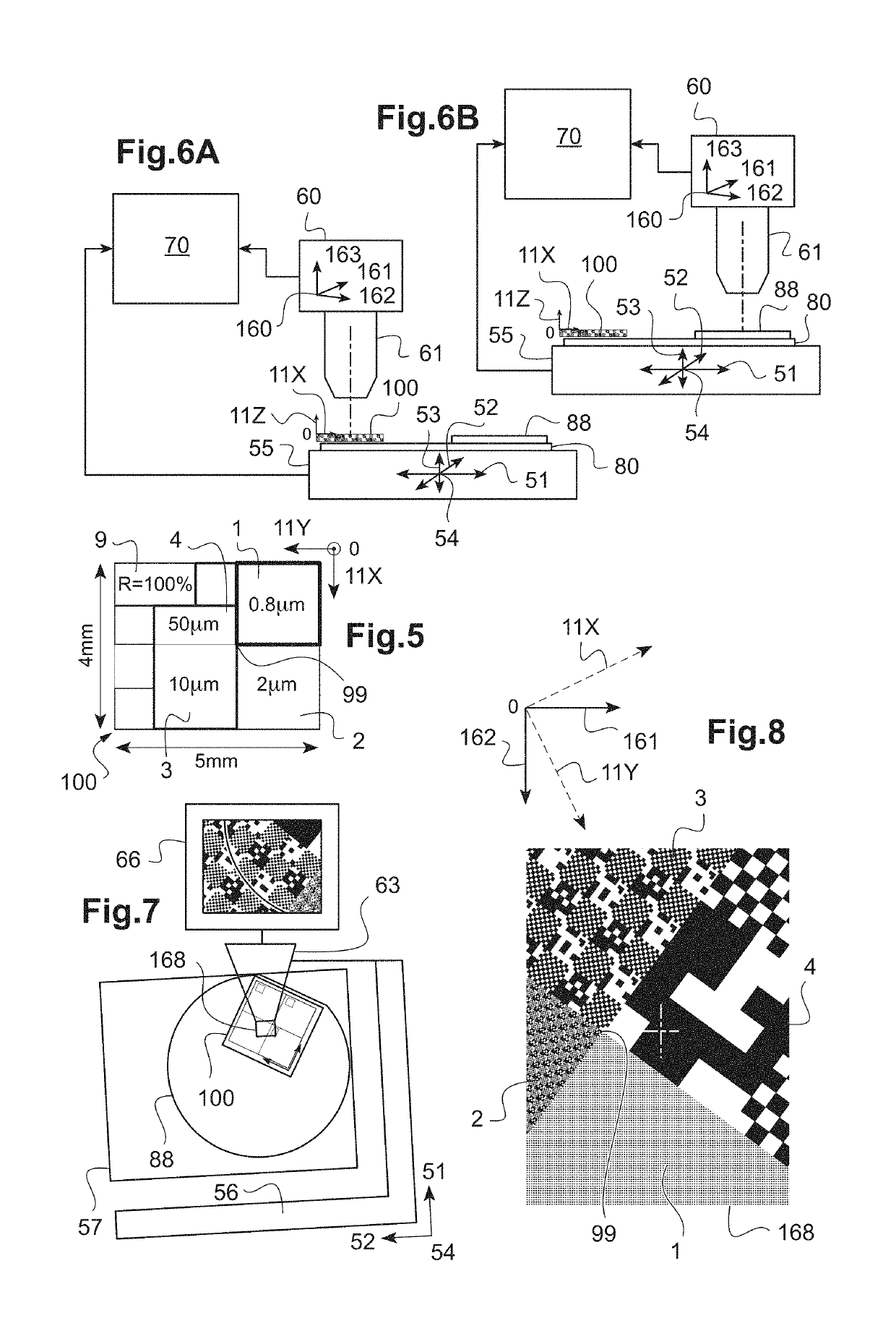
[0048]FIG. 5 schematically represents a macroscopic view of another ...


PUM


Abstract

Disclosed is a micro-localisation device defining a system of spatial coordinates for an imaging instrument. The micro-localisation device includes at least one first zone and a second zone, adjacent to each other, each zone extending spatially over an area of macroscopic size, each zone including an elementary cell or a tiling of a plurality of elementary cells extending over the respective area of the zone, each elementary cell of the first, respectively second, zone including an orientation pattern, a positioning pattern and a periodic spatial pattern, configured to be imaged by an imaging instrument and to determine a position and, respectively an orientation of the imaging instrument in the system of spatial coordinates of the micro-localisation device.

Description

TECHNICAL FIELD OF THE INVENTION[0001]The present invention relates to a spatial marking device and method for a system for characterising a sample.[0002]It relates more specifically to a device for marking in position and in orientation for a microscope or metrology instrument making it possible to obtain a sub-micrometric or even nanometric positioning accuracy and repeatability on the sample.[0003]Finally, it relates to method for marking a metrology or analysis instrument in position and in orientation.BACKGROUND INFORMATION AND PRIOR ART[0004]With the emergence of the nanotechnology era, the capacity to take extremely accurate measurements in order to control the production, operation and ageing of different components on a nanometric scale has become essential. Recurring problems are thus the re-localisation and co-localisation of measurements taken at different instants of time and / or with different measuring instruments. As an example, different types of measurements can be ...

Claims


Application Information

Patent Timeline
IPC IPC(8): G06K9/00G01Q30/04G01Q30/20H04N5/232
CPCG06K9/00134G01Q30/04G01Q30/20H04N5/23218G02B21/26G02B21/34G02B21/365H04N17/002G06V20/693H04N23/61
Inventor ACHER, OLIVIERRICHARD, SIMONGAILLET, MELANIEPODZOROV, ALEXANDERKNOWLES, ADRIAN
Owner HORIBA FRANCE SAS
Why Eureka
Eureka Blog
Learn More