Hydrocarbon detection

a technology of hydrocarbons and detection methods, applied in the field of hydrocarbon detection, can solve the problems of direct threat to ship traffic, ropes, affecting the detection of oil spills, etc., and achieve the effect of facilitating the identification of oil spills

Inactive Publication Date: 2019-05-02
POLARCUS DMCC
View PDF0 Cites 1 Cited by
  • Summary
  • Abstract
  • Description
  • Claims
  • Application Information

AI Technical Summary

Benefits of technology

[0024]The database may be configured to receive digitally signed data from several marine vessels. A national database might contain mandatory spectral signatures of the bunker oil of all vessels entering and / or leaving a national port. This would facilitate identification of oil spills, and might prevent vessels from cleaning bunker tanks in open seas. An international database containing data from merchant ships, survey vessels etc. would be a valuable tool for identifying and classifying pollution, for cleaning up and / or for determining trends regarding oil contamination and synthetic solid particles in the oceans.

Problems solved by technology

Oil spills from fixed and floating production facilities, pipelines and vessels, e.g. vessels cleaning their bunker tanks at sea, may harm birds and marine life and pollute shores.
Other pollution include solid synthetic objects, e.g. ropes, destroyed or abandoned fishing nets or synthetic rubber particles from vehicle tyres.
Some objects, e.g. ropes, may be entangled in a propeller, and are a direct threat to ship traffic.
Other objects, e.g. synthetic rubber particles, degrade slowly and are primarily harmful to birds and marine life offshore and onshore.
Current environmental surveys for offshore areas often involve airplanes, drones and / or satellites, all of which require relatively expensive equipment, e.g. sensitive LIDARs capable of detecting weak return signals.
Thus, current environmental surveys are relatively expensive, and not performed as often as desirable.

Method used


Image

  • Hydrocarbon detection

Examples


Embodiment Construction

[0028]The drawings are intended to illustrate the principle of the invention, and are not to scale. Numerous details known to those skilled in the art are omitted for clarity.

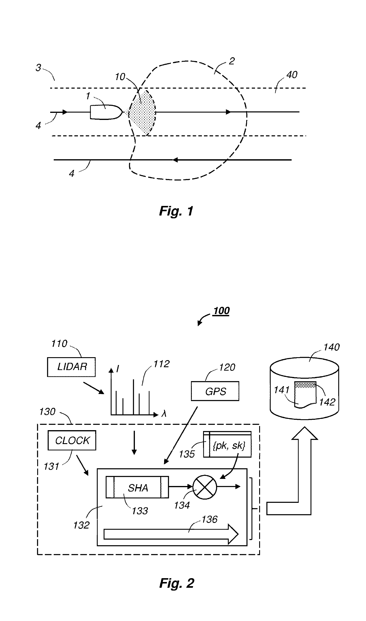
[0029]FIG. 1 shows a marine vessel 1 approaching a polluted area 2 on a sea surface 3. The marine vessel may perform some unrelated task, e.g. a seismic survey, such that the present environmental survey is a bonus at little additional cost. As shown, the vessel 1 travels along a path 4 that might be followed by a seismic survey vessel. However, the path 4 might be any path followed by a merchant ship, cruise ship or other marine vessel over an ocean or along a coast. A detector aboard the marine vessel 1 scans a sector 10, e.g. in front of the vessel. Thus, the marine vessel 1 detects pollution on or at the sea surface 3 in a region 40 along the predetermined path 4.

[0030]The region 40 may include a water column below the sea surface 3 to identify hydrocarbons and solid objects at, as opposed to on, the sea su...


PUM

PropertyMeasurementUnit
wavelengthaaaaaaaaaa
wavelengthsaaaaaaaaaa
distanceaaaaaaaaaa

Abstract

The invention concerns a system (100) for detecting pollution (2) on or at a sea surface (3), wherein the system (100) is adapted for mounting on a marine vessel (1). The system comprises a detector (110) with a LIDAR for providing digital pollution data (112) relating to pollution (2) in a region (40) along a path (4) travelled by the marine vessel (1); a positioning system (120) for providing positioning data; a clock (131) for providing a digital timestamp; and a computer (130) for collecting, combining and storing digital data (141). The computer (130) is configured to execute a secure hashing algorithm (133) on pollution data (112) with associated positioning data and a timestamp to produce a digest, execute an encryption function (134) on the digest using a private key (sk) and to store the data (141) and encrypted digest (142) in a database (140).

Description

FIELD OF THE INVENTION[0001]The present invention concerns a system for remote detection of pollution on or at a sea surface.PRIOR AND RELATED ART[0002]Oil spills from fixed and floating production facilities, pipelines and vessels, e.g. vessels cleaning their bunker tanks at sea, may harm birds and marine life and pollute shores. Other pollution include solid synthetic objects, e.g. ropes, destroyed or abandoned fishing nets or synthetic rubber particles from vehicle tyres. Some objects, e.g. ropes, may be entangled in a propeller, and are a direct threat to ship traffic. Other objects, e.g. synthetic rubber particles, degrade slowly and are primarily harmful to birds and marine life offshore and onshore.[0003]LIDARs (LIght Detection And Ranging) are commonly used detectors for remote detection of oil spills etc. Suitable laser sources emit light in the near UV-range, e.g. 300-400 nm, which has a sufficient energy to excite molecules in the oil spill. The molecules emit fluorescent...

Claims


Application Information

Patent Timeline
Patent Type & Authority Applications(United States)
IPC IPC(8): G01N21/85G01S17/02G01N33/18G01S7/48G01S17/89H04L9/06G06F21/60G01S17/04G01S17/86
CPCG01N21/85G01S17/023G01N33/1833G01S7/4802G01S17/89H04L9/0643G06F21/602G01N33/18G01S17/88H04L9/32G01N21/6456G01S17/86G01S17/00G06F21/60G06F21/64H04L2209/72G01N21/64G01N21/25G01N21/00G01N2021/6417G01N2021/1793G01S17/04G06F21/62G01N33/1826
Inventor GODOY, ERIK
Owner POLARCUS DMCC
Why Eureka
Try Eureka