
An oblique submerged reverse deep rotary tillage device

a rotary tiller and reverse technology, applied in the field of rotary tillers, can solve the problems of heavy-duty soil tillage, high energy consumption, complicated tilling process, etc., and achieve the effects of reducing re-tillage and power consumption, improving tillage depth, and improving tillage depth

Active Publication Date: 2019-05-09
JIANGSU UNIV
View PDF6 Cites 8 Cited by
  • Summary
  • Abstract
  • Description
  • Claims
  • Application Information

AI Technical Summary

Benefits of technology

This patent describes a new type of rotary tillage device called an oblique blade roller. This device has a unique design with rotary blades that bend towards the same direction, allowing for efficient cutting and soil crushing. The device has a high angle between the rotary blades and the tractor, resulting in strong tension force and better soil penetration. The device is especially useful for reducing re-tillage and energy consumption. Additionally, the device can easily cut soil beneath the gearbox and the bearing seat, allowing for deep rotary tilling. Overall, this device has a simple and compact structure and is a significant improvement over other rotary tillage methods.

Problems solved by technology

Soil tillage is a heavy-duty work and consumes a lot of energy.
However, in order to meet the agronomic requirements, the plowed soil needs to be more harrowed, so, the tilling process is complicated, inefficient, energy-consuming and costly.
However, rotary tillage needs more energy, and its performance coverage is relatively poorer compared to plow tillage.
However, the large diameter of the knife roller will make the whole structure bulky and heavy, and the power consumption will increase sharply.
Meanwhile, rotary tilling blades have the minimum dynamic cutting angle, and the resistance of cutting soil is small.
In this way, the value of R is relatively small, and consequently, the rotary cultivator has the advantages of compact structure, but the power consumption will increase sharply with the tilling depth increasing.
Meanwhile, the cutting soil resistance force direction of the knife cylinder points to the front top, and its vertical component force points upward, which will not be helpful for rotary tilling blades piercing soil.
Especially, the blade back will squeeze soil when travel speed increase and leading rotary tillers to bump which influences the stability of tilling depth.
If the horizontal resistance force of the knife roller is bigger than tractor rolling resistance and other horizontal resistances, the tractor will be pushed to slip in the process of cutting soil, and parasitic power will be generated.
It will lead tractor driving system to be destroyed, increase tractor power consumption and lower tractor effective life.
So, submerged reverse rotary tillage can reduce the cutting resistance force, cutting torque, and soil crushing energy consumption.
The phenomenon of hipping will cause re-tillage, and make the working load and power consumption increase rapidly.
The rotary tillers will not able work if the hipping is very serious.
This will make the rotary tillers more complicated and lower transmission efficiency.

Method used


Image

  • An oblique submerged reverse deep rotary tillage device
  • An oblique submerged reverse deep rotary tillage device
  • An oblique submerged reverse deep rotary tillage device

Examples


Embodiment Construction

[0041]Further to the drawings as well as specific examples presented below, but the scope of the invention is not limited to this.

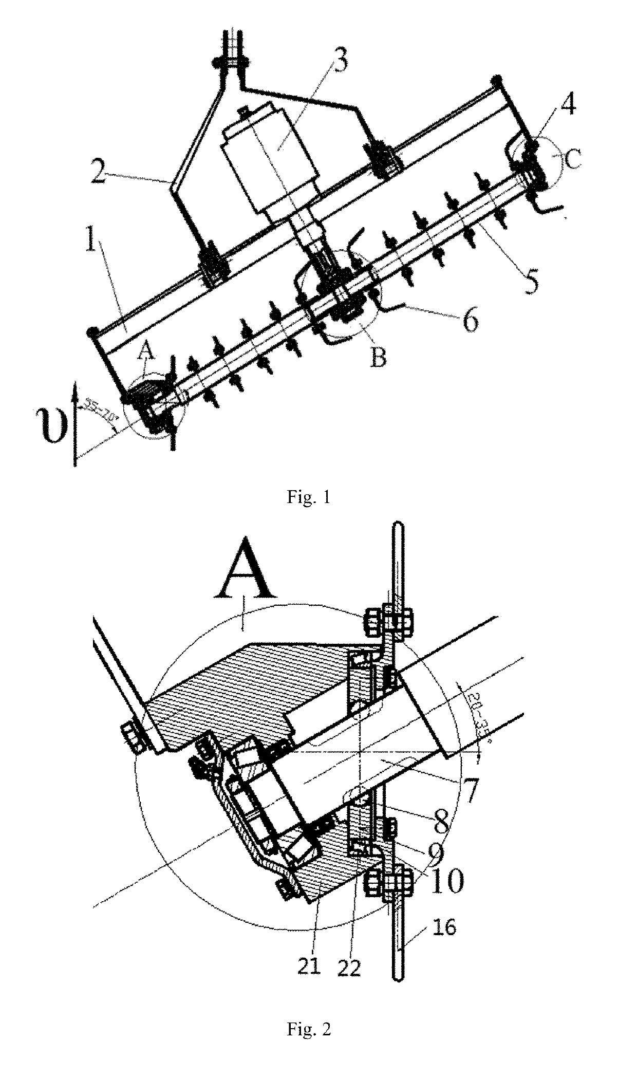
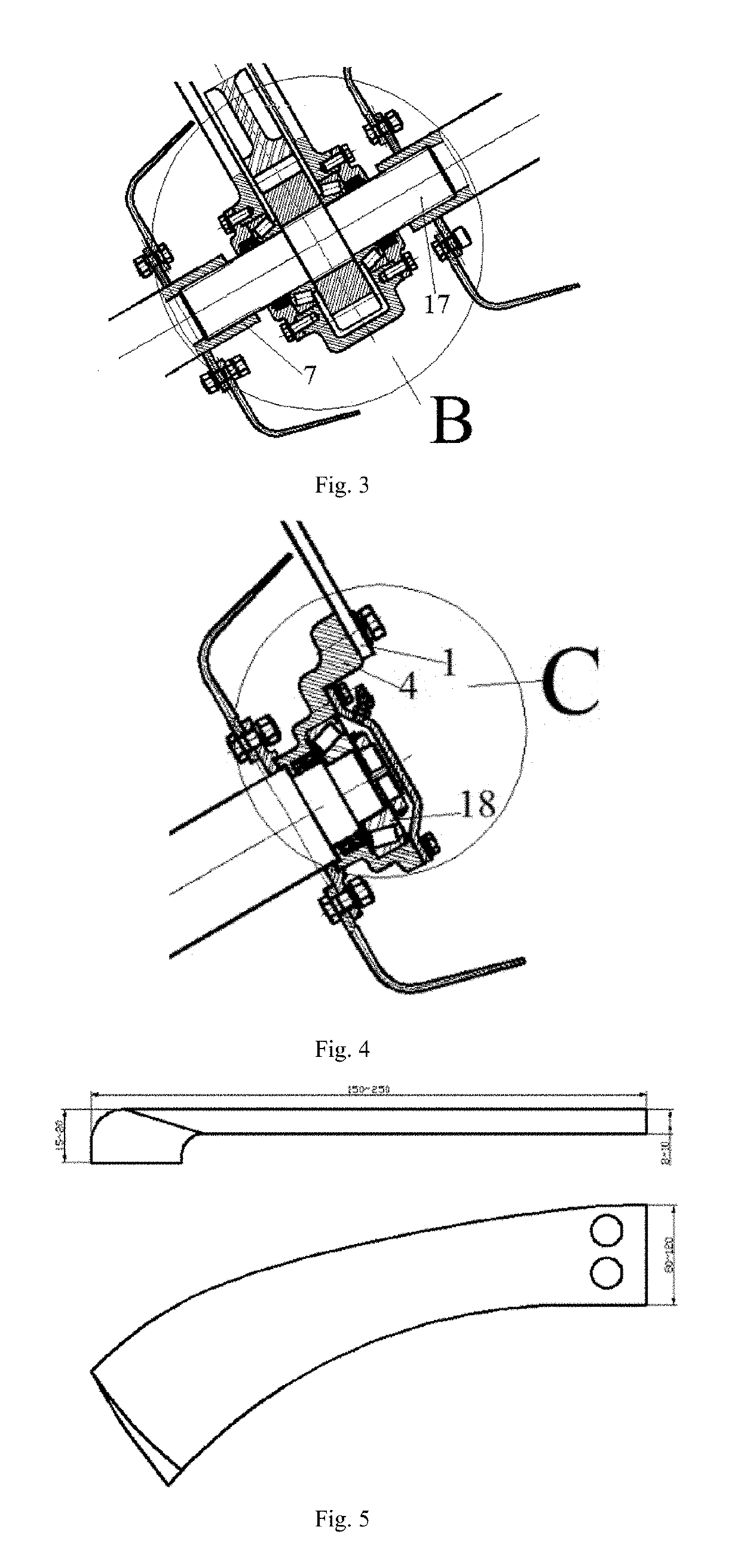
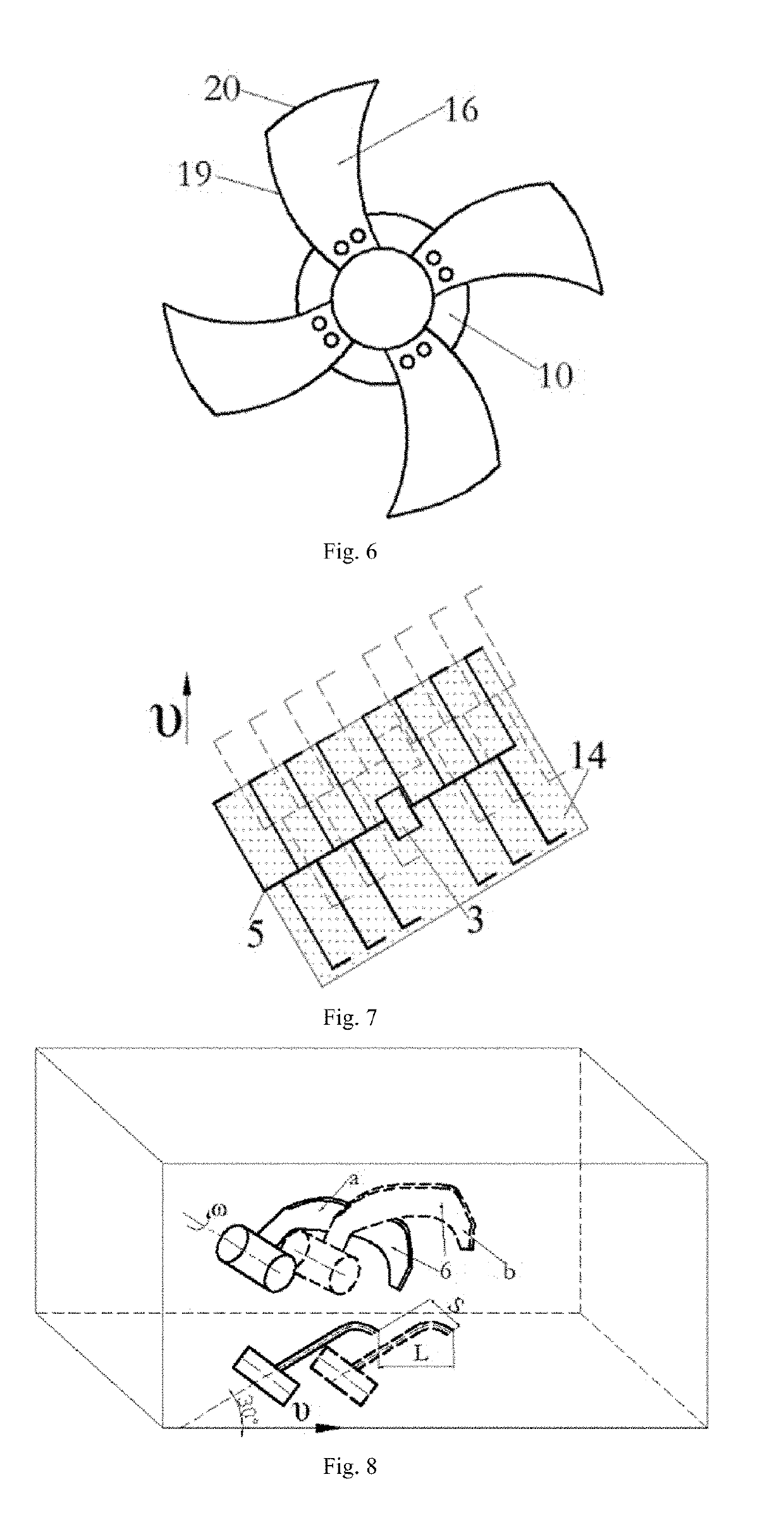
[0042]As shown in FIG. 1, FIG. 3 and FIG. 4, the oblique submerged reverse deep rotary tilling device of the invention includes a stander 1, a mounted frame 2, a gearbox 3 and an oblique blade roller 4. The oblique submerged reverse deep rotary tilling device is connected to the tractor through a mounted frame 2, and the mounted frame 2 is connected to the frame 1. The gearbox 3 is positioned at the center of the device, and the power output shaft of the tractor drives the power input shaft of the gearbox 3 through a universal joint. The power output shaft 17 of the gearbox 3 is a splined shaft, and both ends of the power output shaft 17 are respectively connected with one end of the oblique blade roller shaft 7 on both ends. And the other end of the oblique cutter roller shaft 7 is configured in the bearing 18 located in the bearing seat 4, and the beari...


PUM


Abstract

This invention provides an oblique submerged reverse deep rotary tilling device, which includes a stander, a mounted frame, a gearbox and an oblique blade roller. However, the oblique blade roller is mainly made up of configured rotary blades whose tips bend to the same direction. The angle between the rotary tilling blade roller and the traction speed is 55˜70° while the rotary blade tips are all toward the right side of the traction speed. Side force balance blades are installed to the left side of the oblique blade roller and used to balance the axial component force of the oblique blade roller. The working pattern of this invention is an oblique submerged reverse rotary tillage method. Therefore, there is no soil restriction on the top of the tilling soil clod. Meanwhile, due to cutting soil configured regularly, the right-side soil has been cut when the rotary tilling blades soil begins tilling. The soil is mainly destroyed by tension. Since rotary blades have axial component speed, tilled soil clods will be destroyed mainly by rightward pulling force applied by rotary blades, and the tilled soil clods are mainly thrown to cultivated land. Thus, the invention can reduce secondary tillage and energy consumption. In addition, the invention can avoid interference among gearbox, bearing seat and untilled soil, so the blade roller can easily sink into the ground to achieve deep tillage.

Description

I. TECHNICAL FIELD[0001]The present invention relates to a rotary tiller device adapted for use for the plowing or tilling the soil, grading or leveling the ground, weeding, etc., and particularly concerned with the type of device in which oblique submerged reverse deep rotary tillage is used.II. BACKGROUND ART[0002]Soil tillage is a heavy-duty work and consumes a lot of energy. At present, plowing and rotary tillage are two main ways of soil tillage. By cutting soil orderly, plowing has good tillage performance and meets the demands for deep tillage. However, in order to meet the agronomic requirements, the plowed soil needs to be more harrowed, so, the tilling process is complicated, inefficient, energy-consuming and costly. Rotary tillers have both functions of plowing and harrowing. Meanwhile, it can till stubble, weeds, and green manure crops. Additionally, the tilled land remains level, and furrow slices are fragmented enough after rotary tilling. Therefore, rotary tilling can...

Claims


Application Information

Patent Timeline
Patent Type & Authority Applications(United States)
IPC IPC(8): A01B33/06A01B33/14
CPCA01B33/06A01B33/146A01B33/065A01B33/106A01B33/02A01B33/142
Inventor GAO, JIANMINQI, HUIDONG
Owner JIANGSU UNIV
Learn More