Hydraulic Braking Emergency Utilization for Steering, Braking, Charging Accumulators(s), and/or Work Functions to Reduce or Prevent Engine from Overspeed, Assist Acceleration and/or Unlimited Towing

a technology of hydraulic braking and emergency utilization, applied in the direction of braking systems, braking components, servomotors, etc., can solve the problems of reducing overall system performance and efficiency, damage to the engine and the pump, and heat energy dissipation to the ambient environment, so as to achieve the effect of reducing heat generation in the hydraulic driv

Active Publication Date: 2019-05-09
APPLIED IND TECH
View PDF10 Cites 10 Cited by
  • Summary
  • Abstract
  • Description
  • Claims
  • Application Information

AI Technical Summary

Benefits of technology

[0009]One non-limiting object of the present disclosure is to provide a hydraulic circuit which includes a pump configured to be driven by a prime motor. The circuit further includes a hydrostatic motor fluidly coupled to the pump by first and second lines (i.e., supply and return lines), one or more work function actuators or accumulators fluidly coupled with at least one of the first and second lines, and valving operative to direct at least a portion of pressurized fluid output from the motor during braking operations to at least one of the one or more work function actuators or accumulators. These exemplary non-limiting components thereby reduce or prevent the prime motor (i.e., engine) from over-speeding, as well as minimize heat generation in the hydraulic circuit.
[0010]The non-limiting hydraulic circuits disclosed herein can optionally further include a pressure-reducing valve for converting hydraulic energy to thermal energy, wherein the valving is further operative to direct pressurized fluid from the motor to the pressure-reducing valve during braking. Over-speeding in the prime motor is thereby prevented.
[0013]In accordance with other non-limiting aspects of the present disclosure, there is provided a method of controlling a hydraulic drive of a machine, the hydraulic drive including a pump adapted to be driven by a prime motor of the machine, a motor fluidly coupled to the pump by first and second lines for propelling the machine, and at least one of a work function actuator or an accumulator fluidly coupled with at least one of the first and second lines. The method includes, during machine deceleration, directing at least a portion of pressurized fluid output from the motor to at least one of the work function actuator or the accumulator to thereby prevent the prime motor from over-speeding and to minimize heat generation in the hydraulic circuit.
[0019]In accordance with other non-limiting aspects of the present disclosure, a hydraulic circuit is disclosed which includes a pump configured to be driven by a prime motor, a motor fluidly coupled to the pump by a supply line and a return line, at least one work function circuit fluidly coupled with at least one of the supply and return lines, and valving operative to direct at least a portion of pressurized fluid output from the motor during braking operations to the at least one work function circuit to thereby reduce or prevent the prime motor from over-speeding and / or to minimize heat generation in the hydraulic circuit.
[0026]In accordance with other non-limiting aspects of the present disclosure, the at least one work function circuit of the hydraulic circuit can optionally include an engine control circuit configured to minimize over-speeding in the prime motor, assist in acceleration, and / or permit unlimited towing.
[0036]In accordance with other non-limiting aspects of the present disclosure, there is provided a method of controlling a hydraulic drive of a machine. The hydraulic drive includes a pump adapted to be driven by an engine of the machine, a motor fluidly coupled to the pump by a supply line and a return line and including a high-pressure port side, and at least one work function circuit fluidly coupled with at least one of the supply and return lines. The method can include directing at least a portion of a pressurized fluid output from the high-pressure port side of the motor to the at least one work function circuit and, returning the pressurized fluid back to the high-pressure port side of the motor when the motor is running as a pump; wherein the directing and returning prevents over-speeding in the prime motor and / or minimizes heat generation in the hydraulic drive.

Problems solved by technology

The input torque from the pump transfers to the vehicle's engine and can cause overspeed due to insufficient engine braking power.
The more input torque, the more engine overspeed, and / or excessive overspeed can result in damage to the engine and the pump.
While this approach provides engine overspeed protection to a certain level, the heat energy dissipated to the ambient environment reduces overall system performance and efficiency.

Method used


Image

  • Hydraulic Braking Emergency Utilization for Steering, Braking, Charging Accumulators(s), and/or Work Functions to Reduce or Prevent Engine from Overspeed, Assist Acceleration and/or Unlimited Towing
  • Hydraulic Braking Emergency Utilization for Steering, Braking, Charging Accumulators(s), and/or Work Functions to Reduce or Prevent Engine from Overspeed, Assist Acceleration and/or Unlimited Towing
  • Hydraulic Braking Emergency Utilization for Steering, Braking, Charging Accumulators(s), and/or Work Functions to Reduce or Prevent Engine from Overspeed, Assist Acceleration and/or Unlimited Towing

Examples


Embodiment Construction

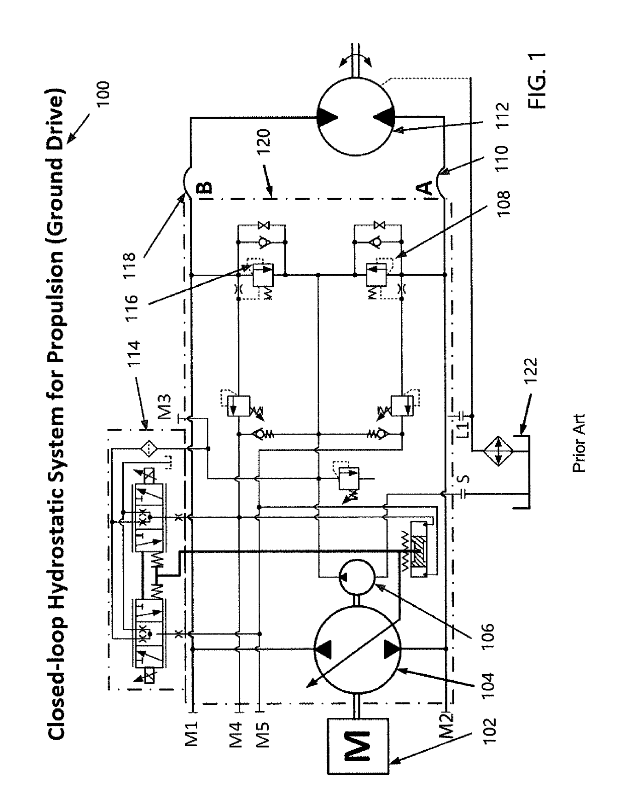
[0050]Referring now in greater detail to the drawings, wherein the showings are for the purpose of illustrating non-limiting embodiments of the invention only and not for the purpose of limiting the invention, FIG. 1 illustrates a typical prior art closed-loop hydrostatic propulsion system 100. The system 100 generally includes a hydrostatic pump 104 fluidly coupled to one or more hydrostatic motor(s) 112 forming a main hydraulic loop 120. The hydrostatic motor(s) 112 can be fixed or variable. The pump 104 is typically connected to a prime motor 102, such as an internal combustion engine or the like, of a machine or vehicle. The prime motor 102 drives the pump 104 to deliver hydraulic fluid to the motor 112 via supply / return lines 110 / 118. The motor 112 drives one or more wheels, tracks, etc. to propel the vehicle.

[0051]A valve 114 (electric proportional / on-off, or hydraulic proportional / on-off, or manual proportional / on-off, or non-servo direct displacement control) inside the pump...


PUM


Abstract

A system and method configured to direct the braking energy from a high-pressure port at the motor side of a hydraulic circuit to emergency steering, braking, accumulator(s) charging, and / or various work functions. The system and method are also configured to return hydraulic fluid back to the same high-pressure port when the motor is running as a pump.

Description

CROSS REFERENCE TO RELATED APPLICATIONS[0001]The present invention claims priority on U.S. Application Ser. No. 62 / 583,298 filed Nov. 8, 2018, which is incorporated herein by reference.[0002]The present disclosure is directed to a system and method configured to direct the braking energy from a high-pressure port at a propulsion motor side of a hydraulic circuit / system and to at least partially use such energy for (a) emergency steering and braking; (b) input into accumulator(s); and / or, (c) various other work functions. Moreover, the system and method of the present disclosure is configured to return hydraulic fluid (e.g., hydraulic fluid, etc.) back to the same port at the propulsion pump side when the motor is running as a pump. The motor may run as a pump, for example: (1) when the engine dies at high machine velocity on flat ground; (2) when the engine dies while the machine travels downhill; (3) during machine deceleration; and / or, (4) when the machine is being towed.BACKGROUN...

Claims


Application Information

Patent Timeline
Patent Type & Authority Applications(United States)
IPC IPC(8): F15B11/08F15B1/02B62D5/30B60T13/14
CPCF15B11/08F15B1/022B62D5/30B60T13/141F15B2211/205F15B2211/4053F15B2211/625F15B2211/6355F15B2211/85F15B2211/8752B60T2270/402B60T17/221B60T17/06F16H61/4157F16H61/431F16H61/4165F16H61/4096
Inventor BABBITT, WENLINGHOFFNER, III, W. E.
Owner APPLIED IND TECH
Why Eureka
Try Eureka