Method and composition for improving lwr in patterning step using negative tone photoresist
Active Publication Date: 2019-05-09
YOUNG CHANG CHEM
View PDF1 Cites 1 Cited by
- Summary
- Abstract
- Description
- Claims
- Application Information
AI Technical Summary
Benefits of technology
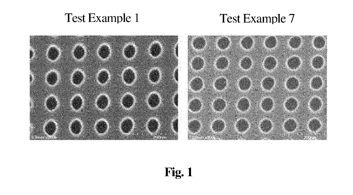
The present invention provides a composition and a process for reducing the LWR (Line Width Roughness) of a negative tone photoresist pattern. This results in improved processing margin and reduced defect rates in semiconductor fabrication. Specifically, the invention allows for fine swelling of the photoresist pattern and trimming of the unexposed surface using an alkaline material, which ultimately reduces LWR and improves depth of focus (DoF) and energy margin (EL margin).
Problems solved by technology
However, as the pattern becomes finer (tens of nm), there occurs a problem in that the processing margin in the fabrication process is decreased owing to the roughness (LWR, line width roughness) of the formed pattern side wall, which is not a problem when the pattern is relatively large (hundreds of nm).
Method used
View moreImage
Smart ImageViewing Examples
Examples
examples 2 to 10
[0051]Respective processing solutions for reducing the LWR of a photoresist pattern were prepared in the same manner as in Example 1 using the components in the amounts shown in Table 1 below.
Login to View More PUM
 Abstract
The present invention relates to a method of reducing the LWR (Line Width Roughness) of a photoresist pattern using a negative tone photoresist during the fabrication of a semiconductor, and more specifically to a composition capable of reducing LWR in order to ensure a higher pattern CDU after a negative tone development process, and a processing method using the composition, thus reducing the LWR, thereby providing better CDU than existing methods.
Description
TECHNICAL FIELD[0001]The present invention relates to a method and composition for reducing the LWR (Line Width Roughness) of a photoresist pattern using a negative tone photoresist during the fabrication of a semiconductor.BACKGROUND ART[0002]With the recent trends toward miniaturization and integration of semiconductor devices, a fine pattern is required. In the formation of such a fine pattern, increasing the fineness of a photoresist pattern through the development of an exposure apparatus or the introduction of an additional process is regarded as efficient.[0003]During the fabrication of a semiconductor in the past, a pattern has conventionally been formed on a semiconductor substrate using an i-line light source at a wavelength of 365 nm, but a light source in a smaller wavelength band is necessary in order to form a finer pattern.[0004]A lithography technique using KrF (248 nm), ArF (198 nm) and EUV (Extreme Ultra Violet, 13.5 nm) light sources has been developed and has bee...
Claims
Login to View More Application Information
Patent Timeline
 IPC IPC(8): G03F7/32G03F7/038G03F7/40
CPCG03F7/327G03F7/038G03F7/40G03F7/325G03F7/405G03F7/0392
Inventor LEE, SU JINKIM, GI HONGLEE, SEUNG HUNLEE, SEUNG HYUN
Owner YOUNG CHANG CHEM
- R&D Engineer
- R&D Manager
- IP Professional
- Industry Leading Data Capabilities
- Powerful AI technology
- Patent DNA Extraction
Learn More Browse by: Latest US Patents, China's latest patents, Technical Efficacy Thesaurus, Application Domain, Technology Topic, Popular Technical Reports.
© 2024 PatSnap. All rights reserved.Legal|Privacy policy|Modern Slavery Act Transparency Statement|Sitemap|About US| Contact US: help@patsnap.com


