Stator and single-phase motor

a single-phase motor and stator core technology, applied in the direction of magnetic circuit rotating parts, magnetic circuit shape/form/construction, windings, etc., can solve the problem of difficult single-phase motor to provide a large torque, and achieve the effect of effectively regulating the relative radial movement of the rotor and the stator core, preventing the development of a gap between the inner-side holding portions and the supports, and preventing turbulen

Inactive Publication Date: 2019-05-09
MABUCHI MOTOR
View PDF0 Cites 3 Cited by
  • Summary
  • Abstract
  • Description
  • Claims
  • Application Information

AI Technical Summary

Benefits of technology

[0020]In this case, the first mating groove portions of the inner-side holding portions of the insulator and the second mating groove portions of the supports of the bearing unit are engaged with each other without a gap in the circumferential direction, and the stator is fitted between the supports. Accordingly, development of a gap between the inner-side holding portions and the supports is prevented. Thus, when a fan for blowing air toward the stator is coupled with the single-phase motor during use, for example, it becomes possible to prevent turbulence in a gap between the inner-side holding portions and the supports. In this way, the fan can be driven by the single-phase motor efficiently.
[0021]Further, the first mating groove portions and the second mating groove portions have a triangular shape in the top plan view. Accordingly, it is possible for the first mating groove portions and the second mating groove portions to exert a radially engaging force. As a result, it is possible to effectively regulate relative radial movement of the rotor and the stator cores.
[0022]According to the present invention, an efficient magnetic circuit can be formed and a large torque can be obtained.

Problems solved by technology

Accordingly, it has been difficult to form an efficient magnetic circuit with respect to magnetic fluxes extending radially and in a radiating manner from the outer peripheral surface of the rotor, making it difficult for the single-phase motor to provide a large torque.

Method used


Image

  • Stator and single-phase motor
  • Stator and single-phase motor
  • Stator and single-phase motor

Examples


first embodiment

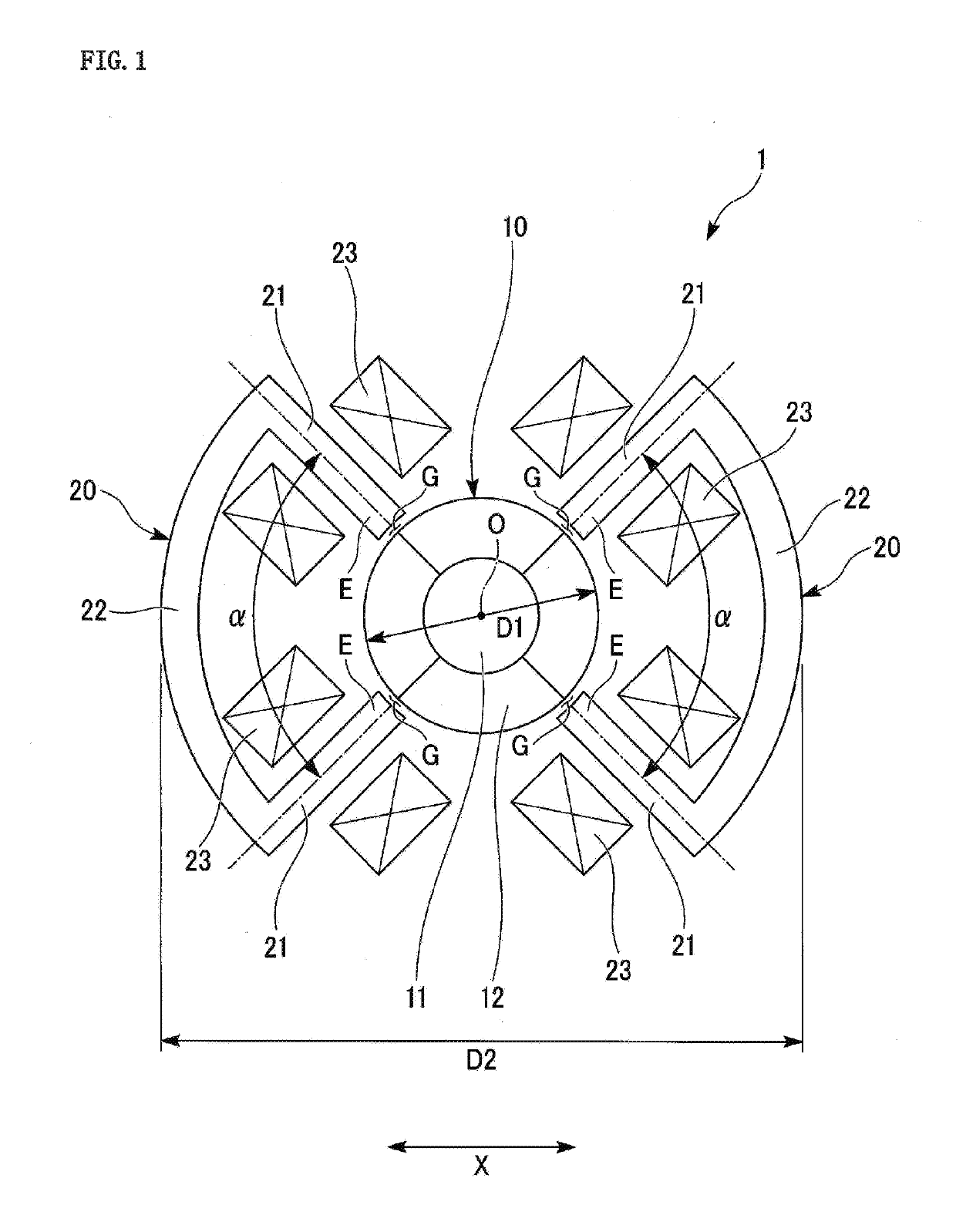
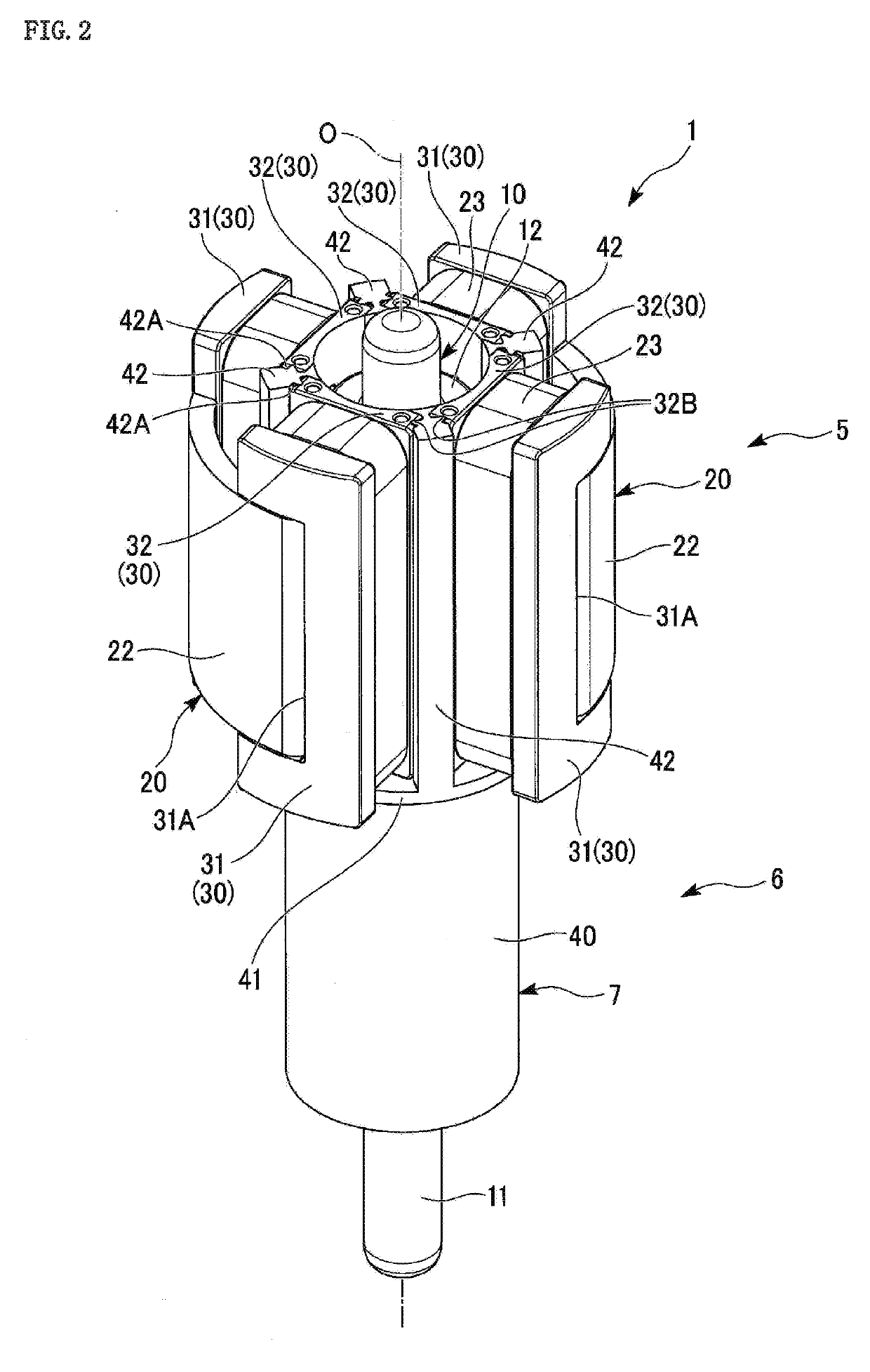
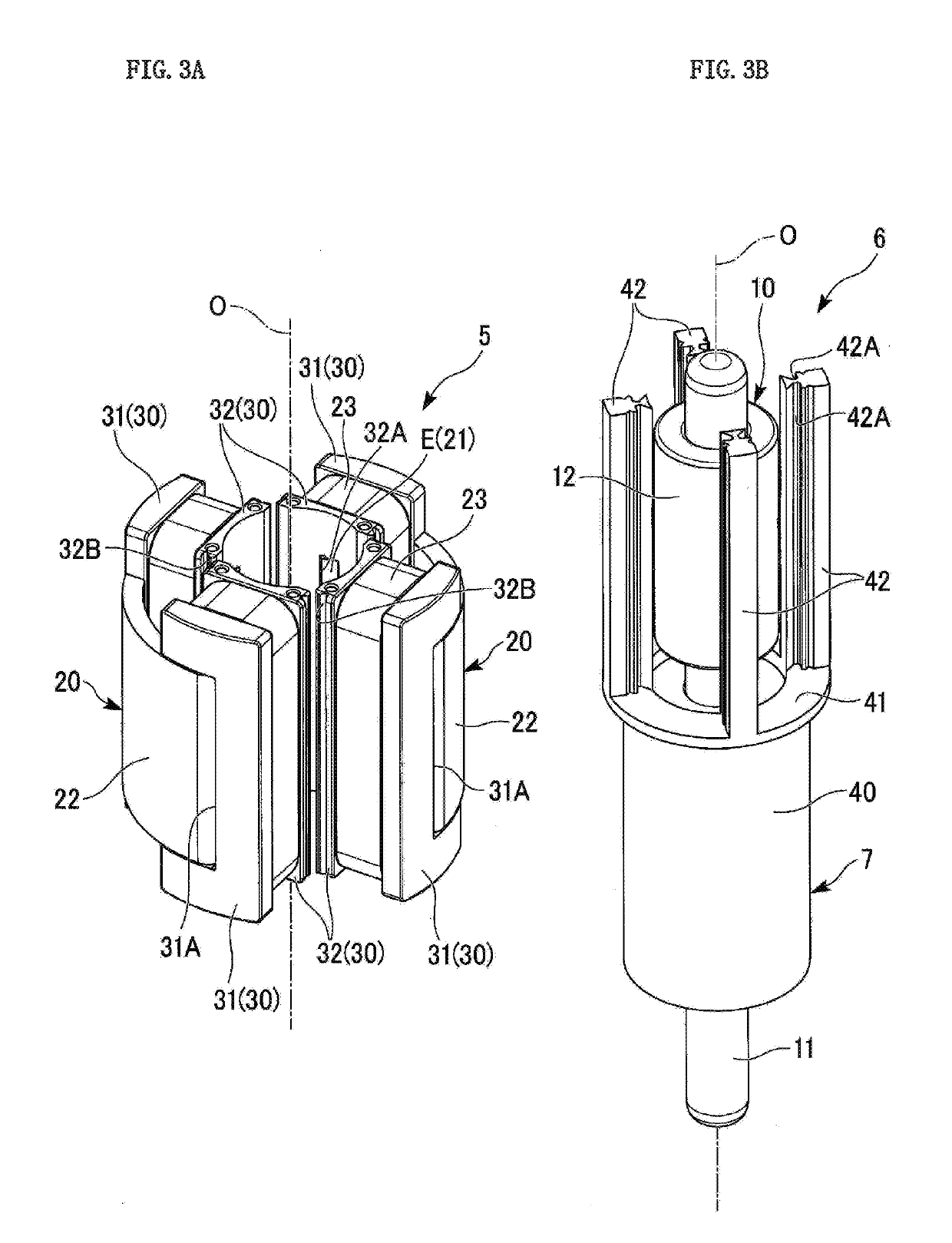
[0029]In the following, a single-phase motor 1 according to a first embodiment of the present invention will be described with reference to FIG. 1 to FIG. 3.

[0030]As illustrated in FIG. 1 and FIG. 2, the single-phase motor 1 is provided with a rotor unit 6 including an axial rotor 10 having a rotating shaft 11 and being rotatably disposed, and a stator 5 covering the rotor 10.

[0031]In the following description, the direction of a central axis line O of the rotating shaft 11 will be referred to as an axial direction. In a plan view from the axial direction, a direction orthogonal to the central axis line O will be referred to as a radial direction, and a direction encircling the central axis line O will be referred to as a circumferential direction. A radial direction will be referred to as a first radial direction X.

[0032]A radial direction toward the central axis line O corresponds to “inner side”. A radial direction away from the central axis line O corresponds to “outer side”.

[00...

second embodiment

[0071]A second embodiment of the present invention will be described with reference to FIG. 4. In the embodiment described below, configurations same as those of the first embodiment are designated with the same signs and their description will be omitted, focusing instead on differences.

[0072]As illustrated in FIG. 4, in a single-phase motor 2 according to the present embodiment, the angle α formed by the pair of arm portions 21 of the stator cores 20 is 80° in the plan view.

third embodiment

[0073]A third embodiment of the present invention will be described with reference to FIG. 5. In the embodiment described below, configurations same as those of the first embodiment are designated with the same signs and their description will be omitted, focusing instead on differences.

[0074]As illustrated in FIG. 5, in a single-phase motor 3 according to the present embodiment, the angle α formed by the pair of arm portions 21 of the stator cores 20 in the plan view is 70°.


PUM


Abstract

Provided is a stator of a single-phase motor with which an efficient magnetic circuit can be formed and a large torque can be obtained. The stator includes a pair of stator cores each having C-shape in a plan view and including distal end portions E disposed proximate to an outer peripheral surface of an axial rotor having a rotating shaft. The stator cores are disposed to opposite to each other with the rotor disposed therebetween in a first radial direction X orthogonal to an axial direction along a central axis line O of the rotating shaft. The stator cores include a pair of arm portions each extending in a radial direction intersecting the first radial direction X, and a base portion. The base portion connects ends of the arm portions on the opposite side from the distal end portions E, and extends in a circumferential direction encircling the central axis line O.

Description

BACKGROUND1. Technical Field[0001]The present invention relates to a stator and a single-phase motor.2. Description of the Related Art[0002]A single-phase motor has been known which, as described in JP-A-2017-123772, is provided with an axial rotor having a rotating shaft and being rotatably disposed, and a pair of C-shaped stator cores having distal end portions disposed proximate to the outer peripheral surface of the rotor. The stator cores are disposed to opposite to each other with the rotor disposed therebetween in a first radial direction of the rotating shaft. Each of the stator cores is provided with a pair of arm portions extending in parallel with the first radial direction.[0003]Generally, such single-phase motors are used in small-sized electric appliances, such as a hair dryer that a user holds by one hand during use. Accordingly, there is a need to reduce the size and weight of the single-phase motors for the sake of convenience of the appliance.SUMMARY[0004]However, ...

Claims


Application Information

Patent Timeline
Patent Type & Authority Applications(United States)
IPC IPC(8): H02K1/14H02K1/27H02K3/18H02K3/32A45D20/12
CPCH02K1/141H02K1/2726H02K3/18H02K3/325A45D20/12H02K1/2733
Inventor TAKAHASHI, TAKUYA
Owner MABUCHI MOTOR
Why Eureka
Try Eureka