Rotating electric machine

Active Publication Date: 2019-05-09
DENSO CORP
View PDF0 Cites 2 Cited by
  • Summary
  • Abstract
  • Description
  • Claims
  • Application Information

AI Technical Summary

Benefits of technology

[0007]According to the present invention previously described, because the improved structure of the rotating electric machine having the three phase windings of not less than two systems such as the first coil and the second coil reduces a timing difference between the line external disturbance voltages of the three phase windings is reduced while maintaining the duty ratio of the line external disturbance voltages, it is

Problems solved by technology

However, when such a pulse voltage is superimposed on a drive voltage to be supplied to the synchronous motor

Method used


Image

  • Rotating electric machine
  • Rotating electric machine
  • Rotating electric machine

Examples


Example

First Exemplary Embodiment

[0042]A description will be given of the rotating electric machine 400 according to a first exemplary embodiment of the present invention with reference to FIG. 1 to FIG. 10A, FIG. 10B and FIG. 10C.

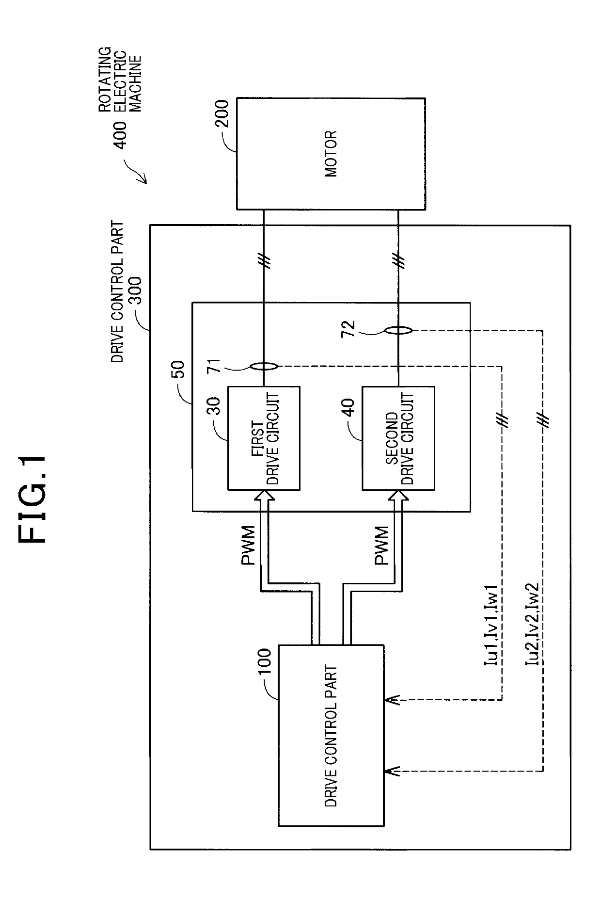
[0043]FIG. 1 is a view showing a structure of the rotating electric machine 400 according to the first exemplary embodiment of the present invention. As shown in FIG. 1, the rotating electric machine 400 according to the first exemplary embodiment has a motor 200 and a drive control part 300.

[0044]The drive control part 300 has a motor drive unit 50 and a control part 100. The motor 200 in the first exemplary embodiment is a synchronous motor with a permanent magnet type or a permanent magnet synchronous motor.

[0045]The motor drive unit 50 has a first drive circuit 30 and a second drive circuit 40. The first drive circuit 30 and the second drive circuit 40 drive dual three phase windings of a stator 220 in the motor 200.

[0046]The control part 200 generates pulse ...

Example

Second Exemplary Embodiment

[0141]A description will be given of the rotating electric machine according to the second exemplary embodiment with reference to FIG. 11. FIG. 11 is a timing chart showing a relationship between adjusted supply voltage instruction signals and the PWM comparison wave CW to be used in the rotating electric machine according to the second exemplary embodiment of the present invention.

[0142]As shown in FIG. 11, in the structure of the rotating electric machine according to the second exemplary embodiment, the adjustment part 132 adjusts the supply voltage instruction signals Du1, Dv1 and Dw1 to the adjusted supply voltage instruction signals Du1*, Dv1* and Dw1*, to be used for the first coil 221 so that the maximum supply voltage instruction signal therein is equal to the maximum PWM comparison wave CW in each PWM period T while maintaining the voltage level difference between the supply voltage instruction signals Du1, Dv1 and Dw1 before the level adjustment...

Example

Third Exemplary Embodiment

[0146]A description will be given of the rotating electric machine according to the third exemplary embodiment with reference to FIG. 12. FIG. 12 is a timing chart showing a relationship between adjusted supply voltage instruction signals and the PWM comparison wave CW to be used in the rotating electric machine according to the third exemplary embodiment of the present invention.

[0147]As shown in FIG. 12, in the structure of the rotating electric machine according to the third exemplary embodiment, the adjustment part 132 (see FIG. 5) adjusts the supply voltage instruction signals Du1, Dv1 and Dw1 to the adjusted supply voltage instruction signals Du1*, Dv1* and Dw1*, respectively to be used for the first coil 221 so that the minimum supply voltage instruction signal therein is equal to a predetermined voltage level Lref between the maximum PWM comparison wave CW and the minimum PWM comparison wave CW in each PWM period T while maintaining the supply volta...


PUM


Abstract

A rotating electric machine has a drive control part and a motor having a stator and a rotor. The drive control part has an external disturbance voltage instruction generation part, a switching signal generation part, first and second drive circuits, a current acquisition part detecting an external disturbance current flowing in three phase winding in each of a first coil and a second coil of the stator, and a phase angle estimation part detecting a phase angle of the rotor of the motor based on the detected external disturbance current. The drive control part adjusts turn-on/turn-off timings of switching signals so as to reduce a timing difference between corresponding line external disturbance voltages in the three phase windings more than the time difference without performing the timing adjustment while maintaining a duty ratio of these line external disturbance voltages to that when the timing adjustment is not performed.

Description

CROSS-REFERENCE TO RELATED APPLICATION[0001]This application is related to and claims priority from Japanese Patent Application No. 2017-214448 filed on Nov. 7, 2017, the contents of which are hereby incorporated by reference.BACKGROUND OF THE INVENTION1. Field of the Invention[0002]The present invention relates to rotating electric machines capable of estimating a phase angle of a rotor thereof.2. Description of the Related Art[0003]In Patent document 1, as a related art, Japanese patent No. 3687603 discloses a technique regarding a rotating electric machine capable of detecting a current variation of a current caused in a synchronous motor when receiving a drive voltage in which a pulse voltage has been superimposed on the drive voltage, and of estimating a phase angle of a rotor. The phase angle indicates a current position of a magnetic pole on the basis of a magnitude of the detected current variation.[0004]However, when such a pulse voltage is superimposed on a drive voltage t...

Claims


Application Information

Patent Timeline
IPC IPC(8): H02K1/26H02K1/28H02K1/16H03K7/08H02P21/00
CPCH02K1/26H02K1/28H02K1/16H03K7/08H02P21/50H02K21/16H02K1/276H02P6/183H02P29/50H02P27/08
Inventor TAKAHASHI, TOMOYA
Owner DENSO CORP
Why Eureka
Try Eureka