Submerged wave energy converter for shallow and deep water operations

a technology of submerged wave energy and deep water, which is applied in the direction of buoyancy control, mechanical equipment, machines/engines, etc., can solve the problem of not recovering energy from the other modes of motion, and achieve the effect of preventing the neutralization of the dynamic pressure differen

Active Publication Date: 2019-05-16
RGT UNIV OF CALIFORNIA +1
View PDF82 Cites 11 Cited by
  • Summary
  • Abstract
  • Description
  • Claims
  • Application Information

AI Technical Summary

Benefits of technology

[0028]The main function of the areal absorber is to prevent pressure exchange between the top and bottom surfaces of the absorber, resulting in a positive and negative alternating irregular sinusoidal load, normal to the absorber area plane, which excites and displaces the absorber. In one embodiment, winglet-like extensions may be attached to the absorber edges in the direction of wave propagation to prevent neutralization of the dynamic pressure difference. The second function of the absorber is to distribute the area load to the point loads applied on the absorber by the bearing points that connect and mount the absorber to the damping elements (e.g. cylinders).
[0029]The hydraulic Power Conversion Chain (PCC) should be capable of up-converting a large, reciprocating mechanical force with a slow linear velocity into a constant mechanical torque that can be used by a generator to produce electricity for consumers. The conversion chain should also be capable of rectifying and smoothing the irregular input of a hydraulic cylinder to a steady pressure and flux. In addition, the accumulators of the PCC can act as an internal energy storage for power input smoothing as well as to provide energy storage that can be used in response to consumer demand from the electrical power grid. The conversion chain can also provide protection from overload or shock loads by altering the path of the hydraulic circuits.
[0037]A process control sub-system may optionally be provided for controlling the operating behavior of a wave energy converter by utilizing passive and active mechanisms in order to improve performance and maximize annual energy production while reducing peak excitation load on the absorber, damping elements, reaction frame, mooring lines and anchors. For example, the system may provide computerized control sub-systems for managing the time-varying and spatially-varying loads on the apparatus to maintain an optimized energy extraction operation and to avoid infrequent damaging loads. A load management sub-system can minimize structural loads on the wave absorbing structure and on the power converting mechanism such as joints, PTO components, etc. including management of peak loads during operations as well as peak loads during extreme events such as storm waves.
[0038]In one embodiment, the wave load management mechanism is capable of increasing or decreasing wave excitation load on the primary absorber structure through shortcutting and thus cancelling of local pressure differential above and underneath the absorber using one or more passive and active apertures embedded in the absorber. The load management subsystem may also be configured for hydrodynamic tuning through adjustments of the natural frequency of the primary absorber through coupled, optimized control of the hydrodynamic properties of added mass and / or operating depth.
[0042]The wave energy converter devices may also be placed in a farm configuration where they are positioned in a direction to capture the average dominant swell of the waves. For example, the devices can be oriented in a linear configuration with mooring points separated by sufficient distances to allow shared mooring points while avoiding wake effects and providing a safe boundary to approach individual devices from every side. Shared mooring anchors may also find material savings compared with two separate, identical anchors by exploiting phase and directional differences in loads as well.
[0045]A further aspect of the technology is to provide a simple, efficient low maintenance system with at least one submerged wave energy absorber, at least one power takeoff unit, at least one restoring force mechanism, and a reaction mechanism.

Problems solved by technology

Since most of the existing technologies focus only on either heave or surge, there is no recovery of energy from the other modes of motion.

Method used


Image

  • Submerged wave energy converter for shallow and deep water operations
  • Submerged wave energy converter for shallow and deep water operations
  • Submerged wave energy converter for shallow and deep water operations

Examples


Embodiment Construction

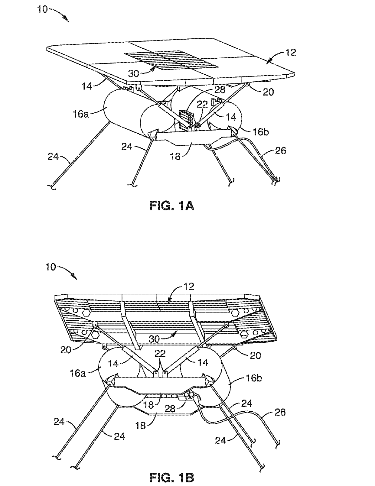
[0062]Referring more specifically to the drawings, for illustrative purposes, embodiments of the apparatus and system for wave energy conversion are generally shown. Several embodiments of the technology are described generally in FIG. 1 through FIG. 8 to illustrate the apparatus and the system characteristics and functionality. It will be appreciated that the methods may vary as to the specific steps and sequence and the systems and apparatus may vary as to structural details without departing from the basic concepts as disclosed herein. The method steps are merely exemplary of the order that these steps may occur. The steps may occur in any order that is desired, such that the method still performs the goals of the claimed technology.

[0063]Turning now to FIG. 1A and FIG. 1B, an apparatus 10 for the conversion of energy stored in ocean waves to electricity that can be transferred to shore and fed into the grid is schematically shown.

[0064]In this illustrative system, a rigid plate ...


PUM


Abstract

A submerged wave energy conversion apparatus and pressurized fluid or electricity production system are provided that harvests energy from a motive force derived from pressure differentials created by the interaction of the system with ocean water. The system is capable of capturing energy from up to six different modes of motion of the absorber body in response to the energy of incident waves. The apparatus has an absorber body that is attached to one or more damping mechanisms like a hydraulic cylinder, a hydraulic circuit that can create useful mechanical torque, a restoring mechanism such as an air spring to restore the absorber system to stable equilibrium, and a buoyant artificial floor to create an opposing reaction force. The apparatus may also have a controller for system monitoring and control, to maintain optimized energy extraction, and for load management to avoid damaging loads.

Description

CROSS-REFERENCE TO RELATED APPLICATIONS[0001]This application claims priority to, and the benefit of, U.S. provisional patent application Ser. No. 62 / 326,814 filed on Apr. 24, 2016, incorporated herein by reference in its entirety.STATEMENT REGARDING FEDERALLY SPONSORED RESEARCH OR DEVELOPMENT[0002]This invention was made with Government support under DE-AC02-05CH11231, awarded by the Department of Energy. The Government has certain rights in the invention.INCORPORATION-BY-REFERENCE OF COMPUTER PROGRAM APPENDIX[0003]Not ApplicableBACKGROUND1. Technical Field[0004]The technology of this disclosure pertains generally to renewable electricity generation, and more particularly to wave energy extraction system and platform using an absorber carpet actuating one or more energy converters.2. Background Discussion[0005]The oceans of the world have long been recognized as a potential continuous and abundant source of natural mechanical energy. Increasing global demand for electricity and the...

Claims


Application Information

Patent Timeline
Patent Type & Authority Applications(United States)
IPC IPC(8): F03B13/20F03B13/14
CPCF03B13/20F03B13/148F05B2260/406F05B2270/18F05B2270/301F05B2210/11F05B2210/40Y02E10/30
Inventor LEHMANN, MARCUSALAM, MOHAMMED-REZABOERNER, THOMASKOJIMOTO, NIGELMURRAY, BRYAN
Owner RGT UNIV OF CALIFORNIA
Why Eureka
Try Eureka