Cylindrical Battery Cell Manufacturing Device Comprising Secondary Crimping Mold

Active Publication Date: 2019-05-16
LG ENERGY SOLUTION LTD
View PDF0 Cites 6 Cited by
  • Summary
  • Abstract
  • Description
  • Claims
  • Application Information

AI Technical Summary

Benefits of technology

[0038]Accordingly, the cap assembly may more stably maintain a sealed state with respect to the open upper portion of the metal can.
[0039]Here, the gasket may include a protruding portion, which protrudes relatively more compared to a remaining portion of the gasket excluding the protruding portion at an outer peripheral portion inside the gasket facing the upper surface of the cap assembly on a vertical section. The protruding portion may have a portion having a flat structure and facing the upper surface of the cap assembly to increase a contact area between the protruding portion and the upper surface of t

Problems solved by technology

Depletion of fossil fuel has brought about a great increase in the price of energy sources and increased interest in environmental pollution.
However, the negative electrode terminal, that is, the crimping portion 142 bonded to the rigid flex substrate, has a relatively smaller area than the positive electrode terminal 14

Method used


Image

  • Cylindrical Battery Cell Manufacturing Device Comprising Secondary Crimping Mold
  • Cylindrical Battery Cell Manufacturing Device Comprising Secondary Crimping Mold
  • Cylindrical Battery Cell Manufacturing Device Comprising Secondary Crimping Mold

Examples


example 1

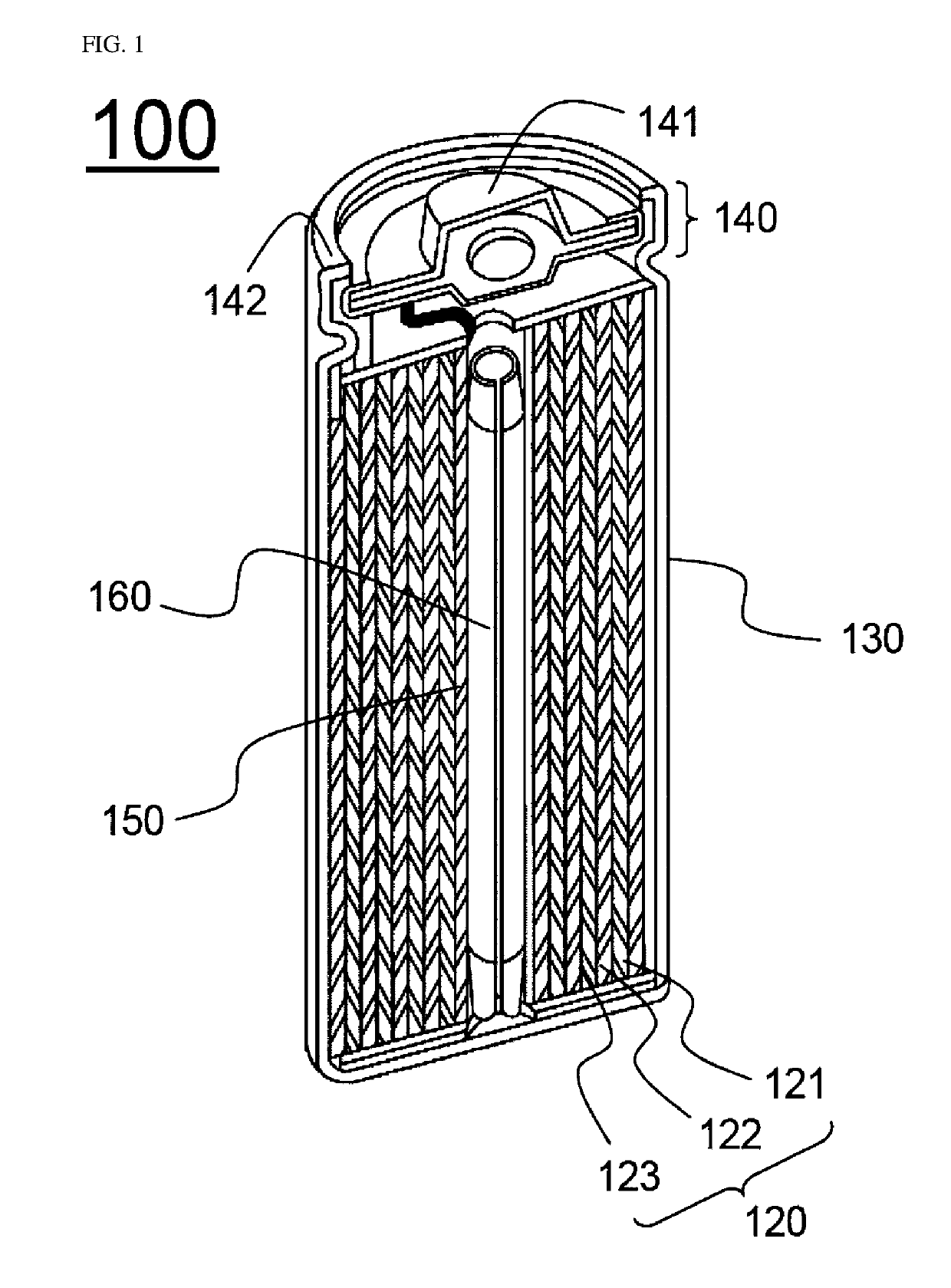
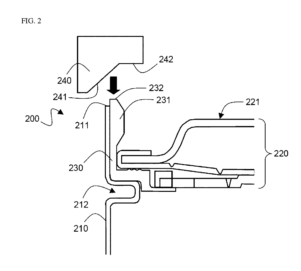
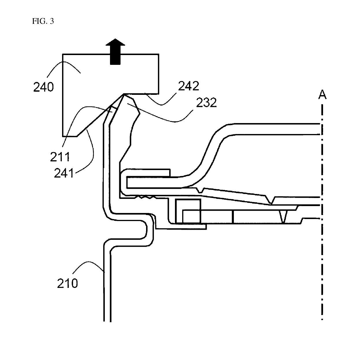
[0083]A beading portion was formed at a portion spaced apart by 4.3 mm from an open upper end portion of a cylinder type metal can having an open upper portion in a state in which an electrode assembly and an electrolyte were housed in the metal can, a primary pressure was applied to the open upper end portion using the primary crimping mold of FIG. 2 in a state in which a cap assembly was seated, and the open upper end portion was bent to have an inclined structure so that a height from the beading portion to the open upper end portion was 3.7 mm. Thereafter, a secondary pressure was applied to the bent open upper end portion by using the secondary crimping mold of FIG. 4 to manufacture a cylinder type battery cell having a crimping portion having a height of 2.55 mm from the beading portion to the open upper end portion, which is about 70% of the height when the primary pressure is applied.

experimental example 1

[0085]A length of the flat section formed by bending the open upper end portion of the metal can in the crimping portion of the cylinder type battery cell manufactured in Example 1 and Comparative Example 1 was measured and the results are shown in Table 1 below.

TABLE 1Length of Flat Section (mm)Example 11.3Comparative Example 10.6

[0086]Referring to Table 1, it can be seen that the length of the flat section in Example 1 manufactured using the secondary crimping mold is greater than that in Comparative Example 1 manufactured using only the primary crimping mold.

[0087]This indicates that a flat section having a longer length is formed in the process of forming the crimping portion by applying the secondary pressure to the open upper end portion of the metal can by the flat portion of the secondary crimping mold, to provide a wider welding area when the cylinder type battery cell is electrically connected to a substrate having a plate type structure such as a rigid flex substrate, and...


PUM


Abstract

The present disclosure provides a cylinder type battery cell manufacturing apparatus which is an apparatus configured to form a crimping portion on a cap assembly coupling portion of a cylinder type battery cell, the manufacturing apparatus including: a primary crimping mold configured to apply a primary pressure so that an open upper end portion of a cylinder type metal can forms an inclination inclined to a central axis of the metal can on a vertical section in a state in which a cap assembly is coupled to the open upper portion of the cylinder type metal can; and a secondary crimping mold configured to apply a secondary pressure to the open upper end portion in which the inclination is formed so that a flat section parallel to a lower surface of the metal can is formed in the crimping portion.

Description

TECHNICAL FIELD[0001]The present disclosure relates to a cylinder type battery cell manufacturing apparatus including a secondary crimping mold.BACKGROUND ART[0002]Depletion of fossil fuel has brought about a great increase in the price of energy sources and increased interest in environmental pollution. Eco-friendly alternative energy sources are a necessity for the next generation. In this regard, a great deal of research into power production methods such as methods of producing nuclear energy, sunlight power, wind power, and tidal power is underway, and a power storage device for efficiently utilizing the produced energy is also attracting much attention.[0003]As the technical development of and the demand on mobile devices increase, the demand on a battery as an energy source has rapidly increased, and a lot of research has been conducted on batteries that can meet various demands[0004]In terms of the shape of batteries, the demand for prismatic secondary batteries or pouch-sha...

Claims


Application Information

Patent Timeline
IPC IPC(8): H01M2/04H01M10/04H01M50/167
CPCH01M2/0408H01M10/0422H01M10/0404H01M10/04H01M10/38H01M6/005Y02E60/10Y02P70/50H01M50/167H01M50/166
Inventor KWON, TAE HYUNLIM, HAE JINSIM, HYEON SOOHEO, HA YOUNGSUNG, JOO HWANKIM, HYOUNG KWONRYU, DUK HYUN
Owner LG ENERGY SOLUTION LTD
Why Eureka
Try Eureka