Coated iron electrode and method of making same

a technology of iron electrodes and coatings, which is applied in the manufacture of electrodes, cell components, final product manufacturing, etc., can solve the problems of limiting the high rate performance, raising temperature, and high manufacturing cost, and achieves a higher quality product and manufacturing method, low cost, and high production efficiency.

Active Publication Date: 2019-05-16
ENCELL TECHNOLOGY LLC
View PDF0 Cites 0 Cited by
  • Summary
  • Abstract
  • Description
  • Claims
  • Application Information

AI Technical Summary

Benefits of technology

[0008]The manufacturing benefits are lower cost, higher volume, continuous process, if desired, and a higher quality product and method for manufacturing compared to the standard pocket electrode design.

Problems solved by technology

Due to its low specific energy, poor charge retention, and high cost of manufacture, however, other types of rechargeable batteries have displaced the nickel-iron battery in most applications.
While the slow formation of iron crystals preserves the electrodes, it also limits the high rate performance.
Nickel-iron cells should not be charged from a constant voltage supply since they can be damaged by thermal runaway.
The cell internal voltage drops as gassing begins, raising the temperature, which increases current drawn and so further increases gassing and temperature.
The methods used in the preparation of the iron electrode (anode) have contributed to the low performance versus cost of the Ni—Fe battery.
The pocket design is not cost effective and is complex in its manufacture.
Pocket design electrodes are also difficult to produce in high volumes, and the energy and power utilization from this design is low.

Method used


Image

  • Coated iron electrode and method of making same
  • Coated iron electrode and method of making same
  • Coated iron electrode and method of making same

Examples


Embodiment Construction

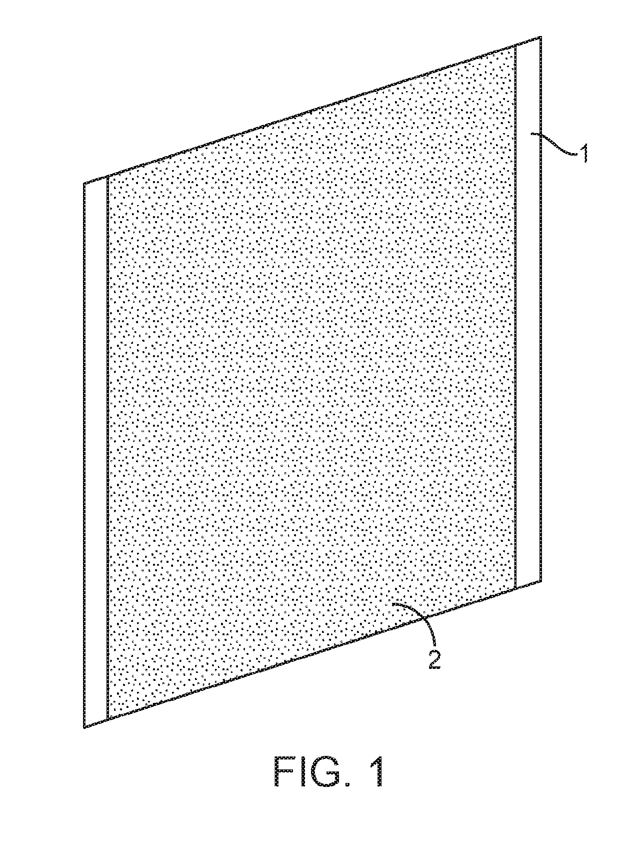
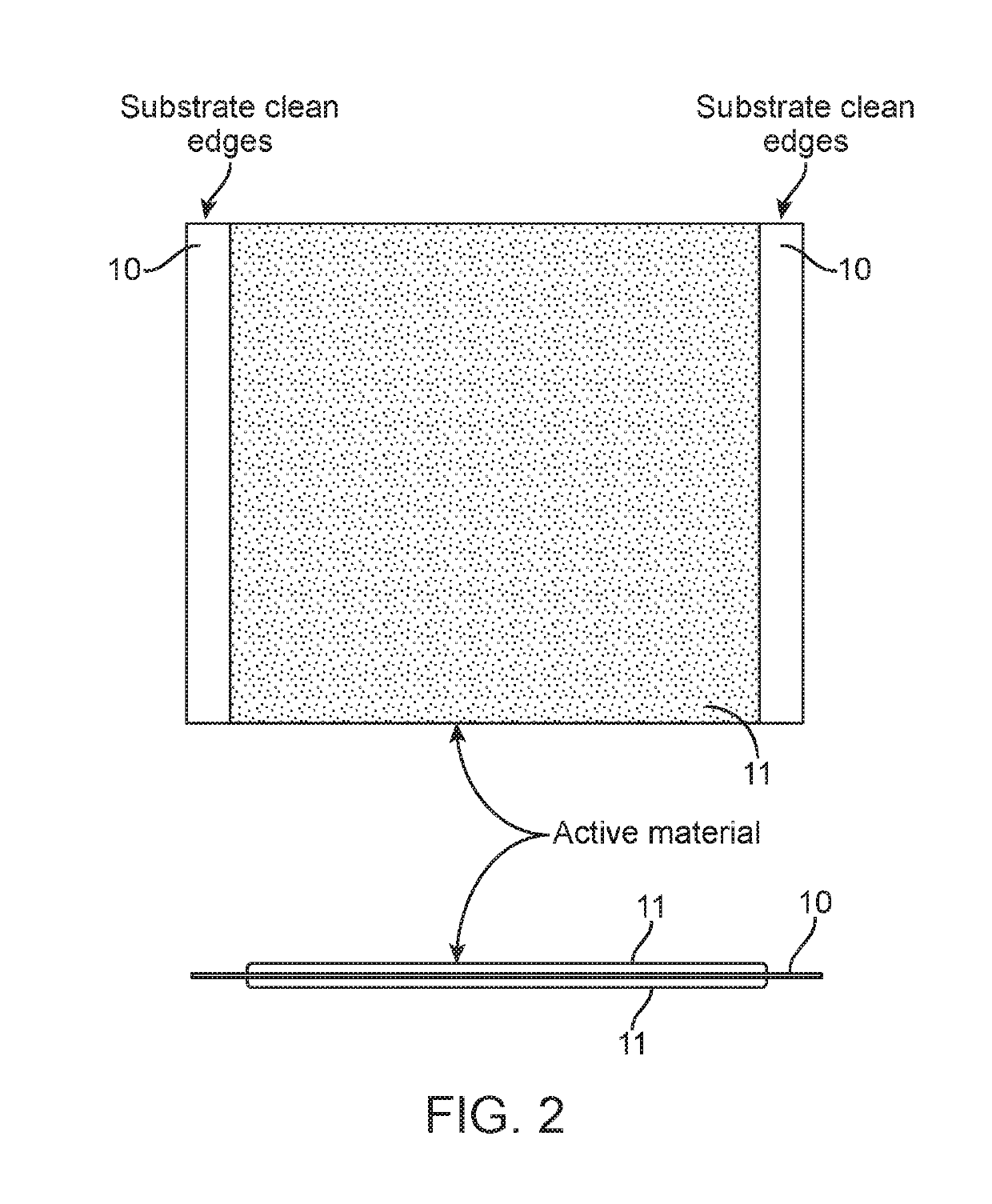
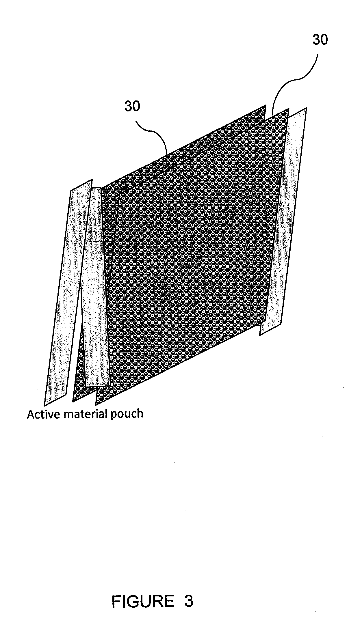
[0013]The invention comprises an iron electrode comprised of a single, coated conductive substrate, prepared by a simple coating process, which can be continuous.

[0014]The substrate is used as a current conducting and collecting material that houses the active material (iron) of the electrode. In the current pocket design, the substrate encompasses the active material and holds the material. Two layers of substrate are therefore required per electrode. In the present invention, a single layer of substrate is used. This single layer acts as a carrier with coated material bonded to at least one side. In one embodiment, both sides of the substrate are coated. This substrate may be a thin conductive material such as a metal foil or sheet, metal foam, metal mesh, woven metal, or expanded metal. For example, a 0.060 inch, 80 ppi, nickel foam material has been used.

[0015]The coating mix is a combination of binder and active materials in aqueous or organic solution. The mix can also contain...


PUM

PropertyMeasurementUnit
porosityaaaaaaaaaa
wt %aaaaaaaaaa
porositiesaaaaaaaaaa

Abstract

Provided is an iron based electrode comprising a single layer of a conductive substrate coated on at least one side with a coating comprising an iron active material and a binder. The iron based electrode is useful in a Ni—Fe battery as the anode. The electrode can also be prepared by continuously coating each side of the substrate with a coating mixture comprising the iron active material and binder.

Description

CROSS REFERENCE TO RELATED APPLICATIONS[0001]This application is a continuation of U.S. patent application Ser. No. 14 / 169,275, filed Jan. 31, 2014, which claims priority to U.S. Provisional Application Ser. No. 61 / 759,777, filed Feb. 1, 2013, which applications are incorporated herein by reference in their entirety.FIELD OF THE INVENTION[0002]The present invention is in the technical field of energy storage devices. More particularly, the present invention is in the technical field of rechargeable batteries using an iron electrode.STATE OF THE ART[0003]Iron electrodes have been used in energy storage batteries and other devices for over one hundred years. Iron electrodes are often combined with a nickel base cathode to form a nickel-iron battery. The nickel-iron battery (Ni—Fe battery) is a rechargeable battery having a nickel (III) oxide-hydroxide cathode and an iron anode, with an electrolyte such as potassium hydroxide. The active materials are held in nickel-plated steel tubes ...

Claims


Application Information

Patent Timeline
Patent Type & Authority Applications(United States)
IPC IPC(8): H01M4/04H01M4/62H01M4/24H01M4/38H01M4/80H01M4/74H01M4/66
CPCH01M4/0404H01M4/621H01M4/248H01M4/38H01M4/808H01M4/74H01M4/661H01M4/0411H01M4/0419H01M2004/021Y02E60/10Y02P70/50
Inventor OGG, RANDY GENE
Owner ENCELL TECHNOLOGY LLC
Why Eureka
Try Eureka