Method for separation of coating from coated glass waste and apparatus suitable for this purpose

a technology of coating and glass waste, which is applied in the direction of magnetic separation, solid separation, gas current separation, etc., can solve the problems of contaminating ground water, affecting the separation efficiency of glass waste, and posing a substantial environmental risk when the coating is removed, so as to achieve efficient separation

Inactive Publication Date: 2019-05-23
GAMMA R&D BV
View PDF0 Cites 2 Cited by
  • Summary
  • Abstract
  • Description
  • Claims
  • Application Information

AI Technical Summary

Benefits of technology

[0015]In a further embodiment of the invention, said apparatus comprises a separator unit whereby a wind flow and / or wind turbulence is applied. Preferably said separator unit also comprises a vacuum generator and a non-ferrous separator. The advantage of implementing these elements is a far more efficient separation.
[0016]In a further embodiment of the invention, said apparatus comprises a grinding mill, preferably comprising steel marbles, a conveyer belt for the automated supply of coated glass and two or more storage containers for the storage of said glass fraction and said lead fraction. Implementation of these components has the advantage of fully automating the process executed with said apparatus.

Problems solved by technology

Whilst this lead glass performs a useful role within a CRT, it poses a substantial environmental risk when the CRT reaches the end of its life and is disposed of.
Studies have shown that when CRTs are disposed of in landfill sites, lead can leach from the glass and contaminate ground water.
This exposes the operator to an environment in which there are airborne heavy metals, which are dangerous to health.
The method is also labor intensive, slow and therefore expensive.
However, this known method has the disadvantage that it does not allow the release of particles that adhere firmly in the glass or that are in principle enclosed in the glass.
The disadvantage of methods known to date for recycling coated glass is that they do not permit a level of purity of the glass such that it can be recycled and be used in a real recycling chain, as disclosed in EP1154860 A1.

Method used


Image

  • Method for separation of coating from coated glass waste and apparatus suitable for this purpose
  • Method for separation of coating from coated glass waste and apparatus suitable for this purpose

Examples


example

[0050]Separating and Isolating a Glass and a Lead Fraction Out of a Discarded CRT Television.

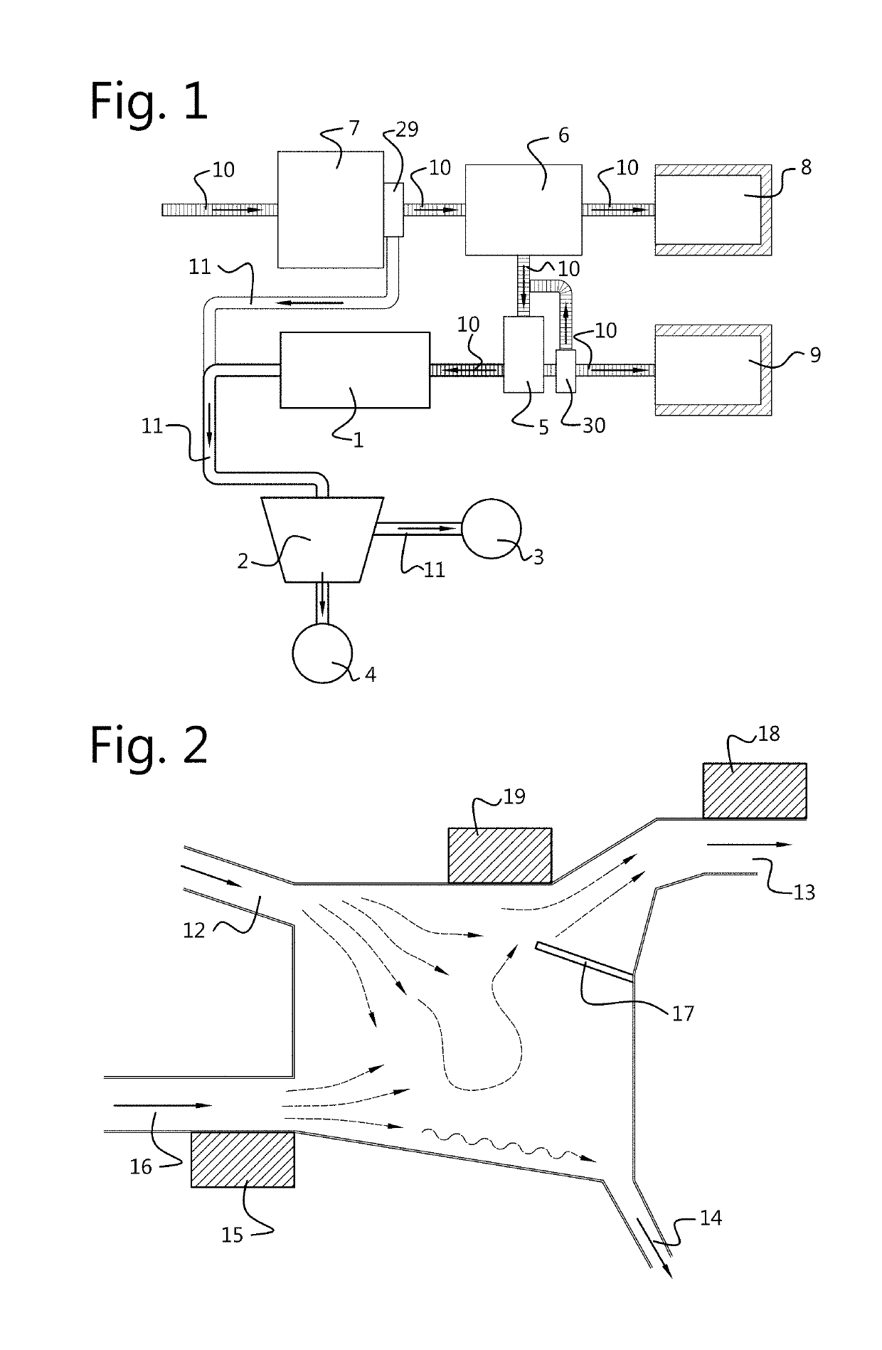
[0051]The example is explained referring to a CRT recycling plant as schematically shown in FIG. 1.

[0052]A discarded CRT television is delivered to a CRT recycling plant. This CRT television is a complex device that has to undergo some manual steps before supplying it to the fully automated CRT recycling process. These manual steps comprise removal of the plastic housing from the device and removal of the main electrical wiring parts. The CRT tube, still containing some metal and plastic elements that are more difficult to remove, is now supplied to the CRT recycling plant by putting it on the first conveyor belt. The CRT tube is carried into a crusher unit where the CRT rube is crushed in smaller parts. CRT glass dust, which can originate from the crushing step, is extracted by a dust extraction system. The resulting parts of the crushing step are not particularly small, however small enoug...


PUM


Abstract

The current invention, in a first aspect, concerns a method for separating a lead component from a lead coated glass, for instance glass from a CRT recycling process. The coated glass is crushed and ground to achieve a finely grained material of a mixture of a glass fraction and a lead fraction. The lead fraction is separated from the glass fraction based upon a difference in specific weight and/or density. In a second aspect the current invention concerns an apparatus for separating a lead component from a lead coated glass, for instance glass from a CRT recycling process. The apparatus is provided with a grinding unit. The apparatus includes a separator unit suited for separation based upon a difference in specific weight and/or density.

Description

TECHNICAL FIELD[0001]The invention pertains to the technical field of coated glass recycling. The current invention relates to a method for removing a coating from glass, and more particularly a method suitable for removing a lead coating from the inside surface of a funnel of a cathode ray tube (CRT).BACKGROUND[0002]About a decade ago, CRTs were frequently used, inter alia, in televisions, computer monitors and monitors for specialist applications, for example, in cash dispensers and industrial applications. A CRT generates images by the acceleration of electrons towards a fluorescent screen. Nowadays, monitors are using more advanced and modern technologies like, among others, liquid crystal displays (LCD), thin film transistor liquid crystal displays (TFT) and organic light emitting diode displays (OLED). With almost no outlets for leaded CRT glass, hundreds of thousands of tons are being accumulated in warehouses across the U.S. alone.[0003]A typical CRT is made from a lead-free...

Claims


Application Information

Patent Timeline
Patent Type & Authority Applications(United States)
IPC IPC(8): B02C23/10B02C23/02B02C23/14B03C1/18B07B4/00
CPCB02C23/10B02C23/02B02C23/14B03C1/18B07B4/00B03C2201/20B03C1/247B03C1/30B02C17/007B02C17/1835
Inventor CRETEER, MIJNDERT CORNELIS ERNST RALF
Owner GAMMA R&D BV
Why Eureka
Try Eureka