Thermal management system

a technology of management system and thermal management system, which is applied in the direction of machine/engine, turbine/propulsion fuel heating, lighting and heating apparatus, etc., can solve the problems of increasing complexity, reducing efficiency, and generating a relatively large amount of heat by different systems

Active Publication Date: 2019-05-23
GENERAL ELECTRIC CO
View PDF4 Cites 24 Cited by
  • Summary
  • Abstract
  • Description
  • Claims
  • Application Information

AI Technical Summary

Benefits of technology

[0008]In one exemplary embodiment of the present disclosure, a gas turbine engine is provided. The gas turbine engine includes a turbomachine; and a thermal management system. The thermal management system includes a first heat exchanger configured to collect heat from the turbomachine during operation; a second heat exchanger; and a thermal transport bus having a heat exchange fluid configured to flow therethrough at a pressure within an operational pressure range, the first heat exchanger and second heat exchanger each fluidly coupled to the thermal transport bus such that the first heat exchan

Problems solved by technology

During operation of the gas turbine engine, various systems may generate a relatively large amount of

Method used


Image

  • Thermal management system
  • Thermal management system
  • Thermal management system

Examples


Embodiment Construction

[0036]Reference will now be made in detail to present embodiments of the invention, one or more examples of which are illustrated in the accompanying drawings. The detailed description uses numerical and letter designations to refer to features in the drawings. Like or similar designations in the drawings and description have been used to refer to like or similar parts of the invention.

[0037]As used herein, the terms “first”, “second”, and “third” may be used interchangeably to distinguish one component from another and are not intended to signify location or importance of the individual components.

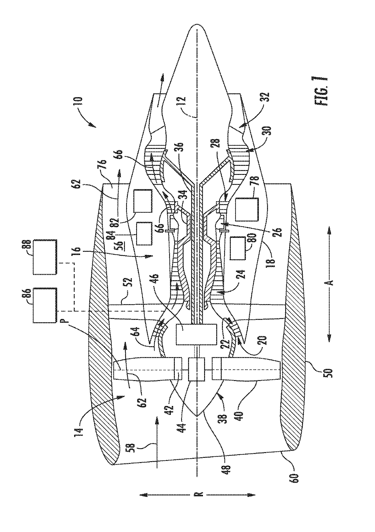
[0038]The terms “forward” and “aft” refer to relative positions within a gas turbine engine or vehicle, and refer to the normal operational attitude of the gas turbine engine or vehicle. For example, with regard to a gas turbine engine, forward refers to a position closer to an engine inlet and aft refers to a position closer to an engine nozzle or exhaust.

[0039]The terms “upstream” and “...


PUM


Abstract

A gas turbine engine includes a turbomachine and a thermal management system. The thermal management system includes a heat source heat exchanger configured to collect heat from the turbomachine during operation; a heat sink heat exchanger; and a thermal transport bus having a heat exchange fluid configured to flow therethrough at a pressure within an operational pressure range. The thermal management system defines an operational temperature range for the heat exchange fluid, the operational temperature range having a lower temperature limit less than about zero degrees Fahrenheit at a pressure within the operational pressure range and an upper temperature limit of at least about 1000 degrees Fahrenheit at a pressure within the operational pressure range.

Description

FIELD[0001]The present subject matter relates generally to a thermal management system, and more specifically to a thermal management system for a gas turbine engine.BACKGROUND[0002]A gas turbine engine typically includes a fan and a turbomachine. The turbomachine generally includes an inlet, one or more compressors, a combustor, and at least one turbine. The compressors compress air which is channeled to the combustor where it is mixed with fuel. The mixture is then ignited for generating hot combustion gases. The combustion gases are channeled to the turbine(s) which extracts energy from the combustion gases for powering the compressor(s), as well as for producing useful work to propel an aircraft in flight and / or to power a load, such as an electrical generator.[0003]In at least certain embodiments, the turbomachine and fan are at least partially surrounded by an outer nacelle. With such embodiments, the outer nacelle defines a bypass airflow passage with the turbomachine. Additi...

Claims


Application Information

Patent Timeline
IPC IPC(8): F02C7/224F02C7/141F28F23/00
CPCF02C7/224F02C7/141F28F23/00F05D2220/323F05D2240/12F05D2260/213F28F27/02F28F2250/06F02C7/14Y02T50/60
Inventor NIERGARTH, DANIEL ALANDELGADO, JR., ADONMILLER, BRANDON WAYNEDE BOCK, HENDRIK PIETER JACOBUS
Owner GENERAL ELECTRIC CO
Why Eureka
Try Eureka