Laser processing device

a processing device and laser technology, applied in metal working devices, other domestic objects, manufacturing tools, etc., can solve the problems of difficult to suitably the adherence of spatters and etc., to avoid the adherence of fumes to the lens, avoid deterioration, and use stably

Active Publication Date: 2019-05-30
HONDA MOTOR CO LTD
View PDF0 Cites 5 Cited by
  • Summary
  • Abstract
  • Description
  • Claims
  • Application Information

AI Technical Summary

Benefits of technology

[0010]The tubular member discharges gas into the through path through the filter in a manner that the gas passes through the filter from an outer surface side of the filter located on the radially outward side, which is an upstream side, toward an inner surface side thereof located on the radially center side, which is a downstream side. The velocity difference of the gas is evened out by resistance or the like passing through the filter. Owing to this, the gas having a reduced velocity difference between locations is discharged into the through path. As a result, between the article to be processed and the lens, a high-pressure layer in which, although the pressure thereof is higher than that of the outside air, the occurrence of a turbulent flow is prevented, is formed. Even when such a high-pressure layer is formed in the through path, an air current that draws in fumes toward the lens beyond the high-pressure layer is not generated. Moreover, it is possible to generate a gentle flow of the gas directed from the high-pressure layer toward the article to be processed.
[0011]Therefore, with this laser processing device, since the above-described high-pressure layer can be formed between the article to be processed and the lens, it is possible to prevent fumes, which are generated from the article to be processed, from moving across the high-pressure layer toward the lens. This makes it possible to effectively avoid the adherence of the fumes to the lens.
[0012]In the above-described laser processing device, it is preferable that the filter is a sintered metallic filter. Such a filter can be stably used because the filter itself can be prevented from being deteriorated even when spatters or the like come into contact therewith. That is, by using the sintered metallic filter, it is possible to improve the durability of the laser processing device and achieve easy maintenance, for example.
[0013]In the above-described laser processing device, it is preferable that the filter has a cylindrical shape whose diameter is constant in an axial direction thereof. In this case, the filter can be formed into a simple shape, which makes it possible to reduce the production cost of the filter and reduce the production cost of the laser processing device accordingly. Moreover, since the diameter of the filter is constant in an axial direction, it is possible to effectively prevent variation in velocity of the gas, which is discharged into the through path through the filter, from occurring in the axial direction. This makes it possible to form the high-pressure layer satisfactorily and avoid the adherence of the fumes to the lens.
[0014]In the above-described laser processing device, it is preferable that the filter is supplied with the gas via a chamber formed between the filter and an inner surface of an outer wall portion of the tubular member, and the gas is supplied to the chamber from a gas supply pipe in a manner that an inflow direction of the gas is oriented along at least part of an outer surface of the filter. In this case, the gas is supplied to the chamber so as to increase the internal pressure thereof while avoiding a situation in which the direction of inflow of the gas is perpendicular to the outer surface of the filter. Owing thereto, the pressure difference of the gas is evened out in the chamber, and then the gas is substantially evenly supplied to the whole of the filter. As a result, it is possible to form the high-pressure layer by more effectively preventing variation in velocity of the gas, which is discharged into the through path through the filter, and thus it is possible to avoid the adherence of the fumes to the lens.

Problems solved by technology

In this case, there is fear that the spatters and fumes carried by the above-described air current traverse the flow of the cross-jet gas and move to the lens side in the through path, resulting in adherence of the spatters and fumes to the lens.
Thus, even with the circulated cross-jet gas, it is difficult to suitably avoid the adherence of the fumes to the lens.

Method used


Image

  • Laser processing device
  • Laser processing device
  • Laser processing device

Examples


Embodiment Construction

[0020]Preferred embodiments of a laser processing device according to the present invention will be described in detail with reference to the accompanying drawings.

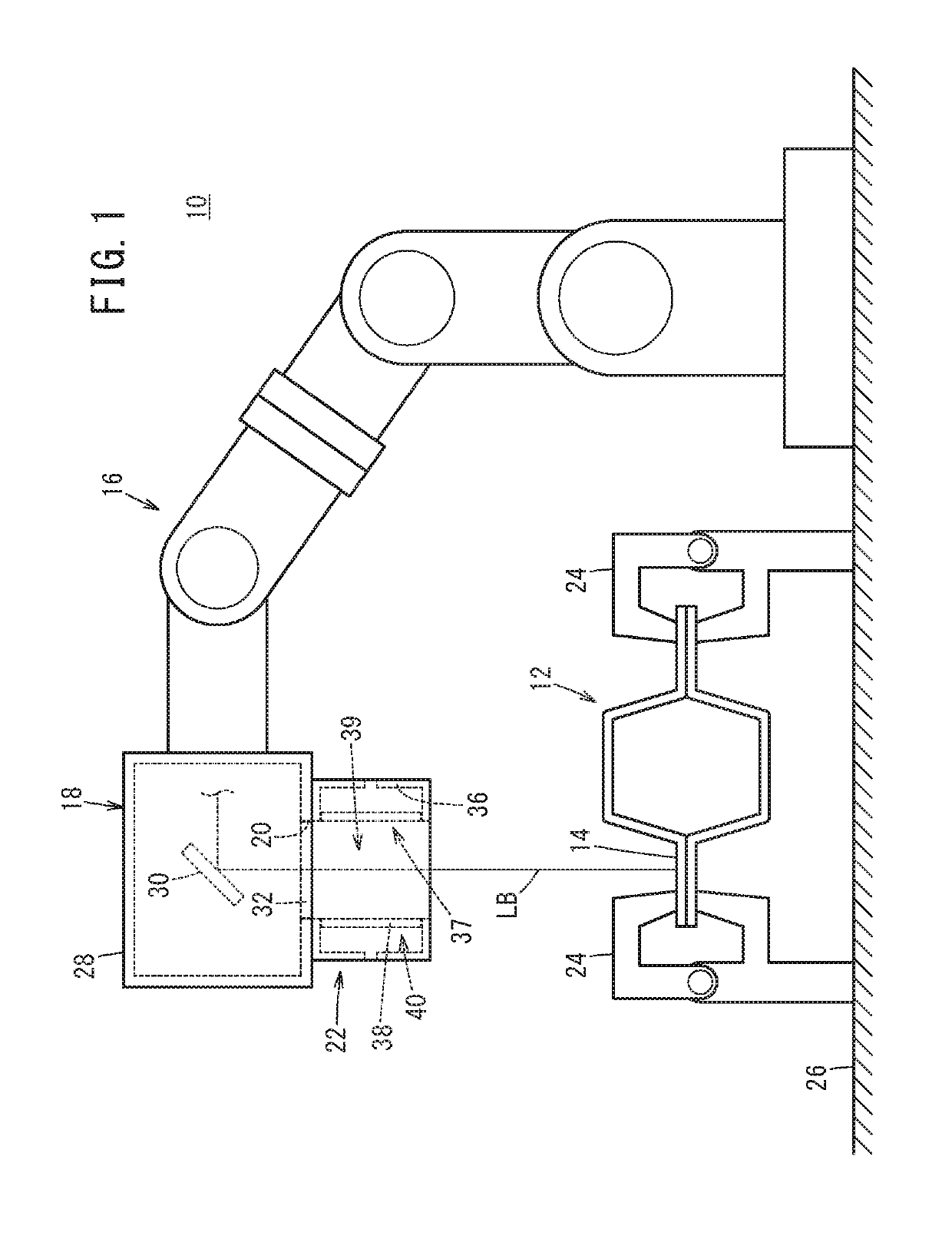
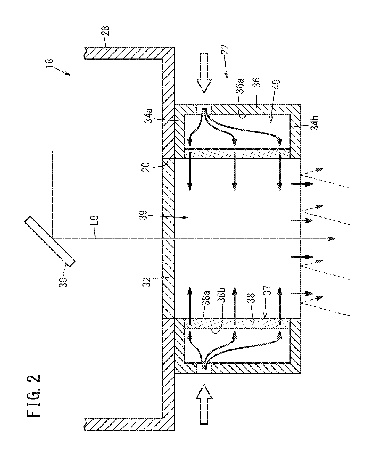
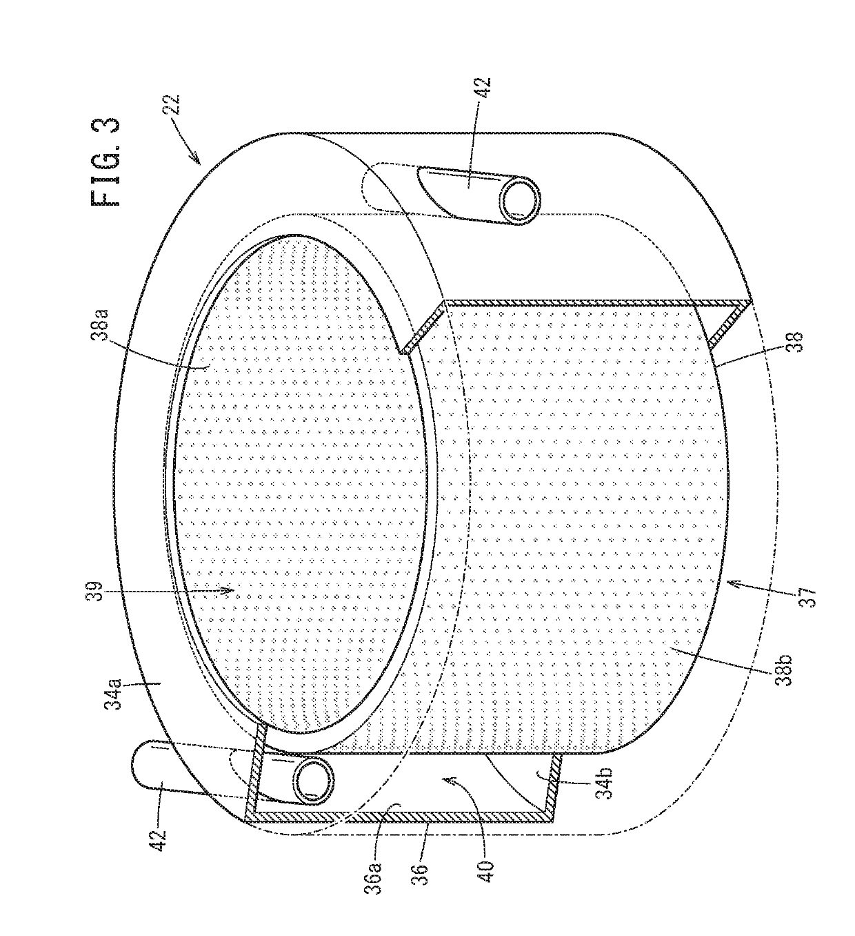
[0021]The laser processing device according to the present invention can be suitably used in a case where welding, cutting, boring, or the like is performed on an article to be processed, by irradiating the same with a laser beam. In the present embodiment, as depicted in FIG. 1, an example in which a laser processing device 10 welds flanges 14 of a set of workpieces 12 serving as an article to be processed, in a state where the flanges are placed in contact with each other, will be described. However, the embodiment is not particularly limited to this example.

[0022]The laser processing device 10 mainly includes, for example, a laser scanner 18 that is supported at the tip of an articulated robot 16, and a tubular member 22 that is detachably attached to a laser output opening 20, which will be described later, of the las...


PUM

PropertyMeasurementUnit
diameteraaaaaaaaaa
flow velocityaaaaaaaaaa
temperaturesaaaaaaaaaa

Abstract

The present invention is a laser processing device wherein adhesion of fumes to a lens can be effectively avoided. The laser processing device is provided with a laser scanner provided with protective glass on a laser output opening, and a cylindrical member having a through path through which the laser output via the protective glass passes formed on the center side in the direction of the radius. A cylindrically shaped filter is disposed on an inside wall part of the cylindrical member facing the through path. The cylindrical member discharges a gas into the through path from the filter.

Description

TECHNICAL FIELD[0001]This invention relates to a laser processing device with a tubular member being interposed between a lens, which is provided at an output opening for a laser beam, and an article to be machined.BACKGROUND ART[0002]In a laser processing device for performing laser welding, laser cutting, and so forth, it is necessary to prevent spatters and fumes which are generated from a workpiece irradiated with a laser beam, from adhering to a lens provided at a laser output opening. The lens here is a generic name for a condensing lens, a protective glass which protects optics, and so forth.[0003]In Japanese Laid-Open Patent Publication No. 01-107994, for example, a laser processing device with a substantially tubular cross-jet gas injection unit interposed between a lens and an article to be machined is proposed.[0004]Specifically, the cross-jet gas injection unit has formed therein a through path through which a laser beam passes, and a discharge pipe that discharges cross...

Claims


Application Information

Patent Timeline
Patent Type & Authority Applications(United States)
IPC IPC(8): B23K26/142B23K26/082B23K26/06B23K26/12B23K26/28
CPCB23K26/142B23K26/082B23K26/0643B23K26/0648B23K26/127B23K26/28B23K26/1476B23K26/26B23K26/38B23K26/244B23K26/382B23K26/706B23K2101/045B23K26/1464B23K26/1462
Inventor AKAHOSHI, HIDEAKIFUJIKURA, KOTAROKANAYA, KOHEIYAMAGUCHI, AKIRASHIMODA, AKIO
Owner HONDA MOTOR CO LTD
Why Eureka
Try Eureka