
Onsite steel rail laser processing engineering vehicle

Active Publication Date: 2019-05-30
WUHAN XINRUIDA LASER ENG +1
View PDF0 Cites 6 Cited by
  • Summary
  • Abstract
  • Description
  • Claims
  • Application Information

AI Technical Summary

Benefits of technology

The present invention provides an onsite steel rail laser processing engineering vehicle that can improve laser processing accuracy and efficiency. The vehicle has a special structural form that allows it to follow the laser processing cart when in laser processing mode, and to safely separate from it when in non-processing mode. The motion executing mechanism can automatically adjust the distance between the two coupling frames, ensuring the width between the wheels on the two sides of the laser processing cart matches the distance between the two steel rails, which avoids serpentine movement and improves processing quality. The vehicle can quickly reach or leave the site, improving equipment utilization efficiency.

Problems solved by technology

With the increase of the speed, traffic volume and axle load of the train, the rate of wear failure of the steel rail is getting faster and faster due to the impact and friction of the wheel.
However, the onsite laser processing equipment adopts a separate structural form, and the optical path (optical fiber), circuit, gas path and water path connected to the laser processing vehicle are complicated to be disassembled and installed before and after the transportation, resulting in low overall usability and reliability of the equipment.
Meanwhile, in some special road sections (such as mountain railways), the power engineering vehicle cannot be placed close to the railway track, and in a case where the power engineering vehicle does not have the railway track driving function, the combined rail laser processing equipment cannot be used.
Further, laser processing can only be performed on one station of a one-sided steel rail by the onsite laser processing equipment at a time, but there are at least four stations on the railway's two steel rails that require laser processing, and laser processing of these different stations must rely on manual adjustment of the position or attitude of the laser processing head, which greatly affects the efficiency of onsite laser processing of the steel rails and results in low level of automation.

Method used


Image

  • Onsite steel rail laser processing engineering vehicle
  • Onsite steel rail laser processing engineering vehicle
  • Onsite steel rail laser processing engineering vehicle

Examples


Embodiment Construction

[0037]For clear understanding of the objectives, features and advantages of the present invention, detailed description of the present invention will be given below in conjunction with accompanying drawings and specific embodiments. It should be noted that the embodiments described herein are only meant to explain the present invention, and not to limit the scope of the present invention. Furthermore, the technical features related to the embodiments of the invention described below can be mutually combined if they are not found to be mutually exclusive.

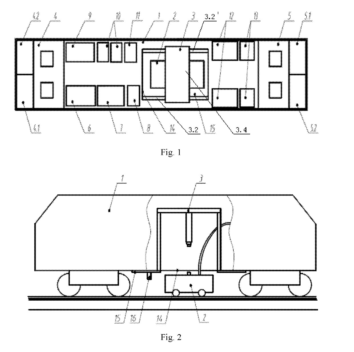
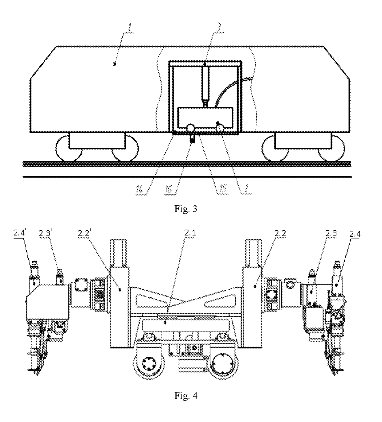
[0038]Referring to FIG. 1 to FIG. 3, the onsite steel rail laser processing engineering vehicle provided by preferred embodiments of the present invention can simultaneously perform laser processing on different parts of two steel rails at a site, and can quickly leave the site after laser processing. The onsite steel rail laser processing engineering vehicle processes with a high degree of automation, strong function and high effici...


PUM

PropertyMeasurementUnit
Structureaaaaaaaaaa
Speedaaaaaaaaaa
Distanceaaaaaaaaaa

Abstract

An onsite steel rail laser processing engineering vehicle, including a laser processing power engineering vehicle and a laser processing cart, the laser processing power engineering vehicle is connected to the laser processing cart; the onsite steel rail laser processing engineering vehicle further comprises a transport mechanism disposed on the laser processing power engineering vehicle; through movement and rotation, the transport mechanism transports the laser processing cart into the laser processing power engineering vehicle or transports the laser processing cart out from the laser processing power engineering vehicle and places it on rails.

Description

BACKGROUND OF THE INVENTIONTechnical Field[0001]The present invention belongs to the technical field of laser processing, and more particularly relates to an onsite steel rail laser processing engineering vehicle.Description of the Related Art[0002]With the increase of the speed, traffic volume and axle load of the train, the rate of wear failure of the steel rail is getting faster and faster due to the impact and friction of the wheel. At present, the methods for improving the life of the steel rails are mainly concentrated on the steel rail heat treatment method and the steel rail material. With the rapid development of laser technology, scholars have applied the laser surface strengthening technology to the surface treatment of the steel rails and achieved good effects.[0003]With the steel rail laser surface strengthening method, not only can fixed-point processing be performed in the production workshop, but also onsite steel rail laser processing can be performed at the railway...

Claims


Application Information

Patent Timeline
IPC IPC(8): E01B31/18B60F1/00B61D15/00C21D1/09C21D9/04
CPCE01B31/18B60F1/00B61D15/00C21D1/09C21D9/04B61L23/045B23K26/08
Inventor ZENG, XIAOYANHU, QIANWUGUO, PINGHUAXU, XIAOMINGJIANG, MINGWANG, DENGZHILI, CHONGYANGMENG, LI
Owner WUHAN XINRUIDA LASER ENG
Learn More