


Quick Research
Generate reliable direction feasibility study reports for your R&D in just a few steps.

Technical Q&A
Discover and master advanced knowledge NOW. Basics, ideas, possibilities, all at once.

Find Solutions
As an expert in R&D theories, this can generate solutions to your technical problems instantly.

Evaluate Feasibility
Analyze your overall solution with one click, know your potential R&D risks in advance.

Monitor Landscape
Get weekly tech updates, stay abreast of the latest tech innovations and key insights.
Muffle furnace and using method thereof
A muffle furnace and shell technology, applied in the field of experimental instruments, can solve the problems of low degree of intelligence, uneven temperature in the muffle furnace, low calcination efficiency, etc., so as to improve the calcination efficiency, work efficiency and equipment utilization efficiency. , Guarantee the effect of calcination effect
- Summary
- Abstract
- Description
- Claims
- Application Information
AI Technical Summary
Problems solved by technology
Method used
Image


Examples
Embodiment 1
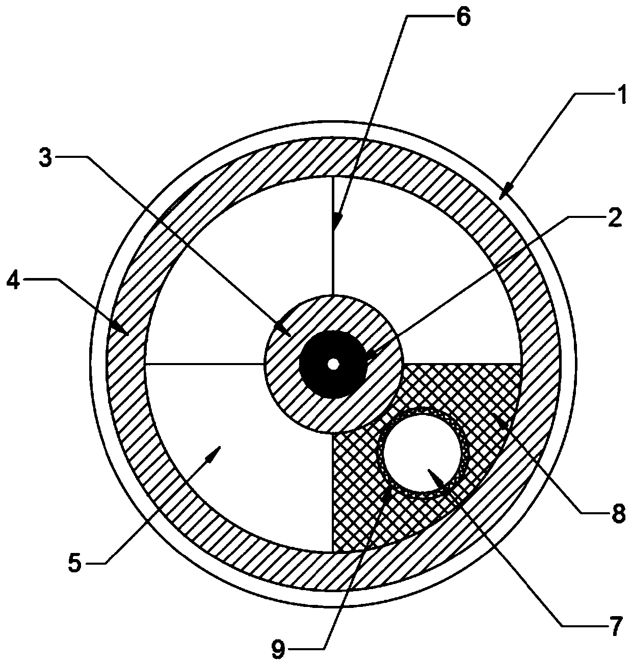
[0040] A muffle furnace, such as figure 1 , figure 2 As shown, it includes a casing 1, a rotating shaft 2 driven to rotate in the shaft center of the casing 1, and at least two partitions 6 fixed on the rotating shaft 2, and the partition 6 divides the interior space of the casing 1. The cavity is divided into at least two calcining areas 5, and a shell door 10 is provided on the side wall of the shell 1, and the top end of the rotating shaft 2 passes through the shell 1 to form a manual rotating part, and the shell door 10 is an arc door, Consistent with the size of the largest calcining area 5, each calcining area 5 is guaranteed to be opened smoothly.
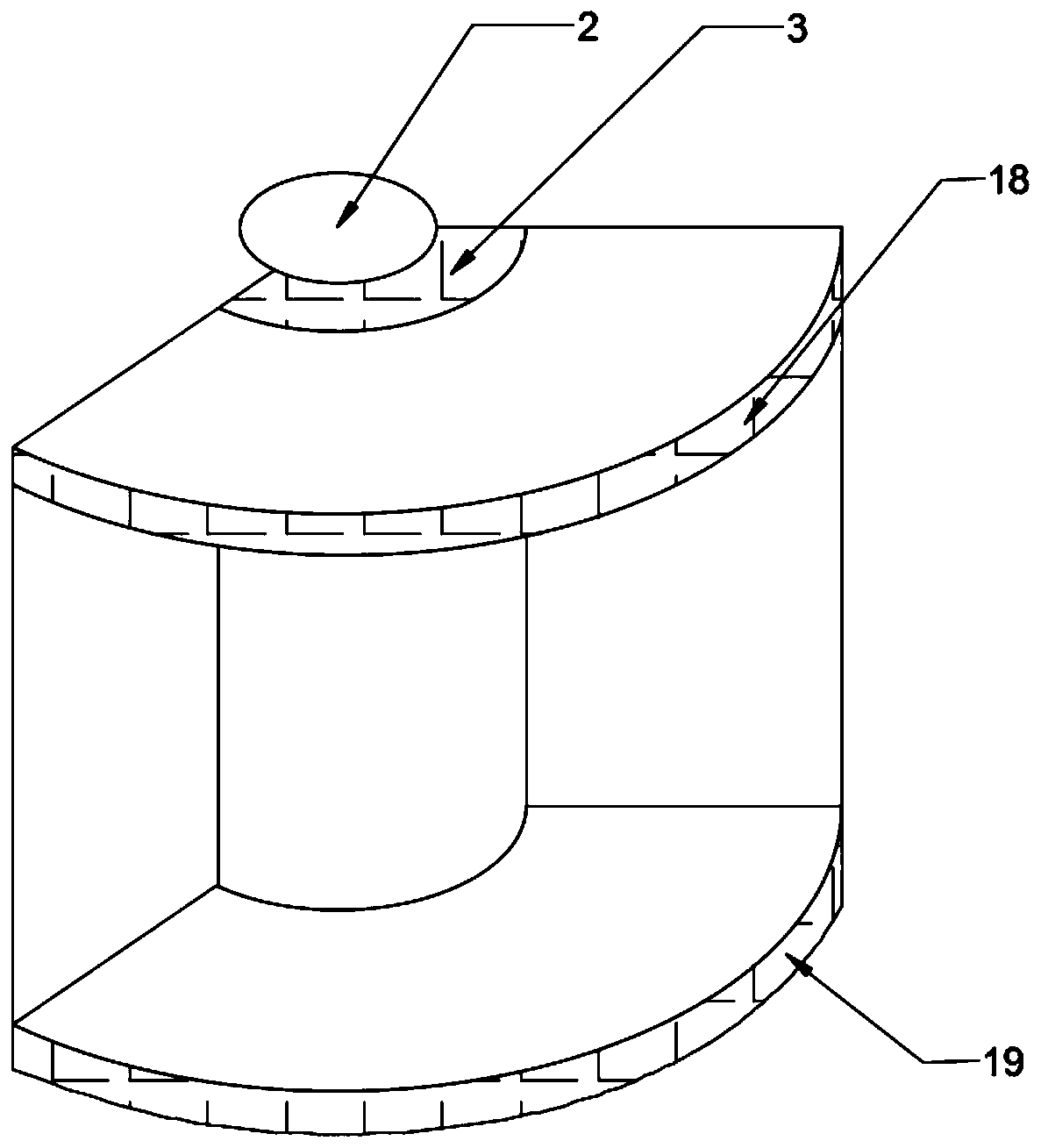
[0041] Each of said calcining zones 5, such as figure 2 , image 3 As shown, the fan-shaped top insulation layer 18 and the fan-shaped bottom insulation layer 19 respectively fixed on the rotating shaft 2, the first insulation layer 3 coated on the side wall of the rotating shaft 2, and the inner wall of the housing 1 a...
Embodiment 2
[0046] This embodiment introduces its preferred structure on the basis of Embodiment 1.
[0047] As a preferred method, such as Figure 4 As shown, the rotating shaft 2 is a hollow rotating shaft, and the air inlet pipe 16 and the air outlet pipe 17 connected to each of the calcination chambers 7 respectively converge in the hollow area of the rotating shaft 2 to communicate with the air inlet main pipe 12 and the air outlet main pipe 13 . The hollow rotating shaft is selected and the air inlet main pipe 12 and the air outlet main pipe 13 are arranged in the hollow part, which can simplify the pipeline and make the overall structure more concise.
[0048] As a preferred manner, the air inlet main pipe 12 and the air outlet main pipe 13 are connected with control valves 21, the air inlet main pipe 12 is connected with combustible atmosphere, and the air outlet main pipe 13 is connected with ventilation equipment. The flammable atmosphere can promote calcination and improve ...
Embodiment 3
[0056] This embodiment introduces its intelligent control system on the basis of Embodiment 1 and Embodiment 2.
[0057] The intelligent control system such as Image 6 As shown, it includes a data acquisition module for collecting temperature and atmosphere in each calcination chamber 7, a main control module, a controller module and a safety alarm module for receiving the data of the data acquisition module and analyzing and processing them; the data The acquisition module is communicatively connected to the input end of the main control module, and the controller module and the safety alarm module are communicatively connected to the output end of the main control module;
[0058] The data acquisition module includes a temperature sensor and an atmosphere sensor fixed in each of the calcining chambers 7;
[0059] The main control module is a STM32F101 series single-chip microcomputer;
[0060] The controller module includes a heating wire controller, a rotating shaft cont...
PUM
 Abstract
Description
Claims
Application Information
 - R&D Engineer
- R&D Manager
- IP Professional
- Industry Leading Data Capabilities
- Powerful AI technology
- Patent DNA Extraction
Browse by: Latest US Patents, China's latest patents, Technical Efficacy Thesaurus, Application Domain, Technology Topic, Popular Technical Reports.
© 2024 PatSnap. All rights reserved.Legal|Privacy policy|Modern Slavery Act Transparency Statement|Sitemap|About US| Contact US: help@patsnap.com