
Aircraft joint with a curable composite bushing

a composite bushing and aircraft technology, applied in the direction of mechanical equipment, rotary machine parts, transportation and packaging, etc., can solve the problems of poor seating of the fastener when installed in the hole, inability to transfer the applied load of the fastener, and increase the overall cost of assembly process, so as to achieve convenient storage and quick installation

Active Publication Date: 2019-05-30
AIRBUS OPERATIONS GMBH
View PDF9 Cites 5 Cited by
  • Summary
  • Abstract
  • Description
  • Claims
  • Application Information

AI Technical Summary

Benefits of technology

The present invention relates to an aircraft structural joint that prevents the attachment fastener from radial displacement during mounting. The joint comprises a curable composite bush made of reinforcement fibers and a hollow cylindrical body with corrugations that improve its compressibility. A third structural component may further be included to displace the first component and receive the protruding fastener. This invention ensures secure and reliable attachment of the structural components in an aircraft assembly.

Problems solved by technology

In the assembly of aircraft structures, machining and drilling of such made to order solid bushing parts to the required accuracy is a precision process and therefore takes time and requires a stop in the assembly, therefore increasing overall costs of the assembly process.
Sometimes the prepared solid bushing or the hole may not correspond to the dimensions of the hole exactly due to hidden irregularities in the surface of the hole itself, which results in a poor seating of the fastener when installed in the hole.
Incorrect seating of the fastener in the hole results in the fastener not transferring the applied load fully when the aircraft is in operation, which has static and fatigue implications.
This conservative approach ultimately leads to a design with a higher number of fasteners required to transfer a given load, thus leading to a higher degree of redundancy, however the structural assembly will also be more costly to manufacture, heavier and require more maintenance due to the increased attachment part count.
Furthermore, in some cases the hole may be so irregular that redundancy will not suffice for the degree of incorrect seating of the fastener, leading to the hole and the solid bushing needing to be reworked and or even the component to be scrapped.
In addition, the use of solid bushings of various sizes requires storage and asset management, which takes up space of the assembly floor and resources.
Furthermore, the process of fitting a solid bush into the existing bore may itself result in damage to the assembly, particularly in the case of composites.
This again may require rework which can be time consuming and therefore can increase costs.

Method used


Image

  • Aircraft joint with a curable composite bushing
  • Aircraft joint with a curable composite bushing
  • Aircraft joint with a curable composite bushing

Examples


Embodiment Construction

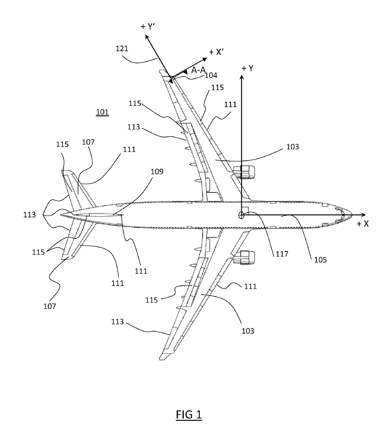
[0021]With reference to FIG. 1, an aircraft 101 is shown with a wing 103 (also referred to as an airfoil) extending approximately horizontally through a fuselage 105. A further wing 107 (also referred to as the horizontal tail plane) extends approximately horizontally from either side of a rear portion of the fuselage 105. Yet a further wing 109 (also known as the vertical tail plane) extends vertically from an upper rear portion of the fuselage 105.

[0022]The wings 103, 109, 107 and the fuselage 105 may be formed of structural assemblies joined together by structural joints which function to restrain at least a pair of assemblies from moving relative to one another once the joints have been fastened, in other words, the pair of assemblies are fixedly attached to one another. Each structural assembly may itself be formed of smaller structural assemblies joined together by a further number of joints.

[0023]The wings 103, 107, 109 each have a leading edge 111 and a trailing edge 113, an...


PUM

PropertyMeasurementUnit
diameter Dfoaaaaaaaaaa

Abstract

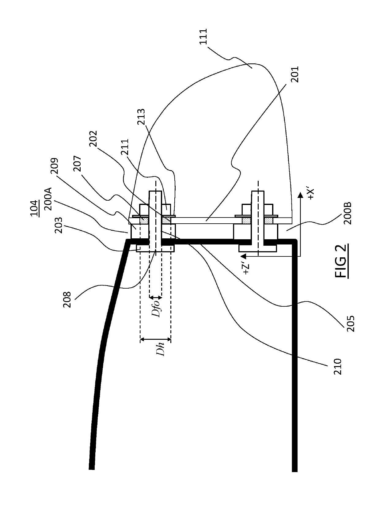
An aircraft structural joint comprising a first structural component provided with an attachment hole that is configured to receive an corresponding attachment fastener provided by a second structural component; a curable composite bush compressed and cured between an outer diameter of the attachment fastener and the attachment hole when the first component is mounted to the second component, wherein the curable composite bush, when cured, prevents radial displacement of the attachment fastener within the attachment hole.

Description

CROSS-REFERENCES TO RELATED APPLICATIONS[0001]This application claims the benefit of the Great Britain patent application No. 171970.6 filed on Nov. 28, 2017, the entire disclosures of which are incorporated herein by way of reference.FIELD OF INVENTION[0002]The present invention relates to a curable composite bushing for an aircraft joint, an aircraft joint, an aircraft structural assembly incorporating such an aircraft joint and a method and tool for installing a curable composite bushing.BACKGROUND OF THE INVENTION[0003]During aircraft structural assembly, it is known to attach two or more components together at a joint by drilling and installing one or more fasteners in predetermined hole positions after the components are mounted at a fixed position relative one another. Once the fasteners are installed the joint is made and a larger structural assembly is formed. It is known that solid bushings or bushes can be used during the assembly of structural joints and assemblies. They...

Claims


Application Information

Patent Timeline
Patent Type & Authority Applications(United States)
IPC IPC(8): F16C33/20B64C3/50
CPCF16C33/201F16C33/208B64C3/50F16C2208/04F16C2208/82B64C3/26B64F5/10Y02T50/40
Inventor LORENZ, FLORIANSHAPI, DUSTIN
Owner AIRBUS OPERATIONS GMBH
Learn More