Artificial heart and its drive unit

Active Publication Date: 2019-06-06
CENT HOSPITALIER UNIV VAUDOIS C H U V
View PDF0 Cites 1 Cited by
  • Summary
  • Abstract
  • Description
  • Claims
  • Application Information

AI Technical Summary

Benefits of technology

[0010]This aim is achieved by an artificial heart including a pump of the type of pump discussed above which thus comprises a housing defining a substantially spherical cavity and comprising four vascular connectors, namely two inlet connectors and two outlet connectors to connect the pump to the pulmonary and systemic circulation. A rotatable disc is housed within the pump housing and secured to rotate about a fixed axis passing through the center of the spherical cavity. Two oscillating palettes are mounted to rotate about a diameter of the rotating disk, perpendicular to the fixed axis. These two palettes are connected together and are arranged on both sides of the rotatable disc, in a diametrically opposed fashion, to create two pumping units comprising each two variable sized chambers in fluid communication with one inlet and one outlet connector respectively. The pump is provided with constrain means configured to cause an oscillating movement of each oscillating palette relative to the rotatable disc, when the pump is operating, in order to produce two concurrent suction strokes simultaneously with two concurrent discharge strokes, so a

Problems solved by technology

Congestive heart failure is a major and growing health problem.
Despite the improvement of conventional medical therapy, there remains a large group of patients who have poor prognosis and require more aggressive techniques to increase their quality of life and life expectancy.
This last approach is rapidly evolving due to the inadequate number of useable donor hearts available.
However, the lack of pulsatility has been correlated to a decrease of right heart recovery, as well as an increase of valve and capillary dysfunction.
The remaining problems are caused by the formation of thrombus and haemolysis which is caused by the rotation of mechanical component of the pump.
Accordingly, the configuration of the pump's drive unit brings the disadvant

Method used


Image

  • Artificial heart and its drive unit
  • Artificial heart and its drive unit
  • Artificial heart and its drive unit

Examples


Example

EXAMPLE

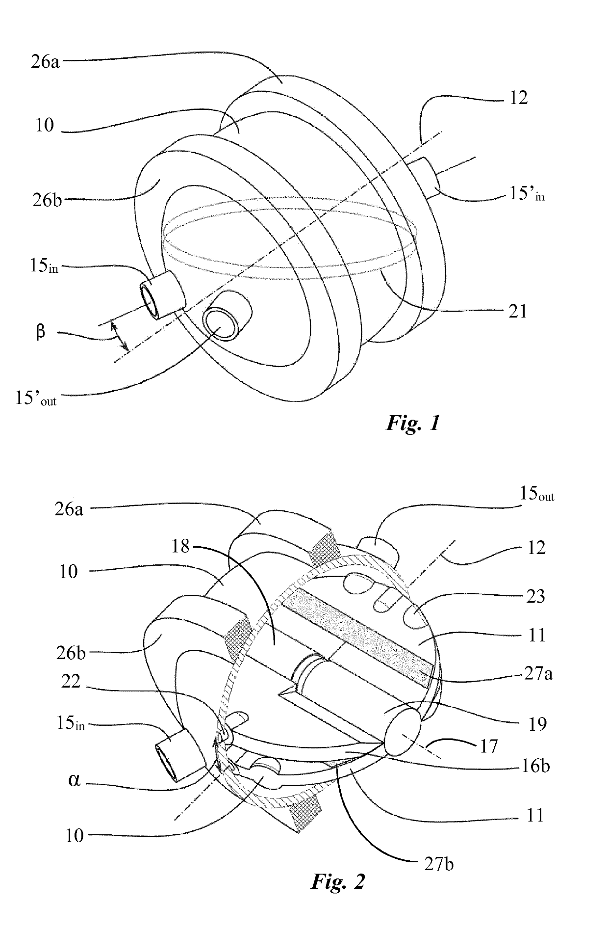
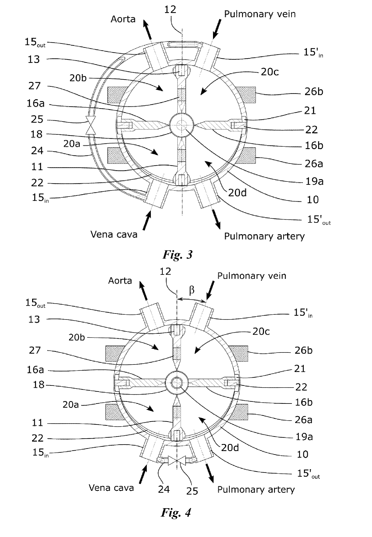
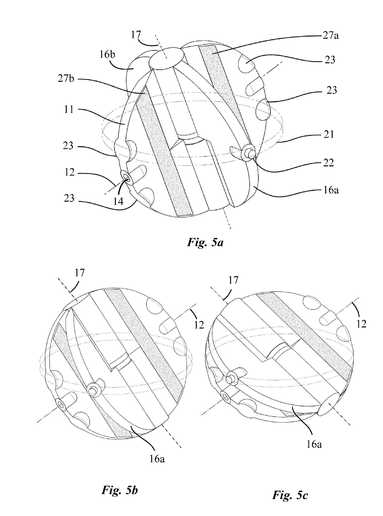
[0044]Here is presented an experimental prototype as a specific example. As mentioned above, the heart is a double pump consisting of a spherical cavity split into four chambers, like the human heart chambers, by two rotating disks. The first disk has one degree of freedom and rotates around a fixed axis passing through the center of the sphere with an angle of θ0 above the equatorial plane. The second disk has two degrees of freedom as it rotates about an axis of rotation which can itself rotate about the center of the sphere within the equatorial plane. A revolute joint links both disks in a direction perpendicular to their respective primary axis of rotation. The overall system has one degree of freedom and a movement imposed to one disk entrains the other one, producing a change in the volume of the chambers.

[0045]In the present prototype, a brushed DC motor (RE 35 graphite brushes 90 watt, Maxon Motor AG, Sachseln, Switzerland) with a 14:1 planetary gearhead is coupled w...


PUM


Abstract

There is described an artificial heart comprising a pump, the pump comprising a housing (10) defining a substantially spherical cavity and comprising four vascular connectors (15in, 15out, 15′in, 15′out), namely two inlet connectors (15in, 15′in) and two outlet connectors (15out, 15′out) to connect the pump to the pulmonary and systemic circulation. A rotatable disc (11) is mounted within the housing (10) and secured to rotate about a fixed axis (12). Two oscillating palettes (16a, 16b) are mounted to rotate about a mobile axis (17) movable within a plane perpendicular to the fixed axis (12), wherein said palettes (16a, 16b) are connected together and are arranged on both sides of the rotatable disc (11), in a diametrically opposed fashion, to create two pumping units comprising each two variable sized chambers (20a, 20b, 20c, 20d) in fluid communication with one corresponding inlet and outlet connector respectively. The pump is provided with constrain means (21) configured to cause an oscillating movement of each oscillating palette (16a, 16b) relative to the rotatable disc (11), when the pump is operating, in order to produce simultaneously two suction strokes and two discharge strokes, so as to pump blood from the inlet connectors (15in, 15′in) into one chamber (20a, 20c) of each pumping unit while expelling blood from the other chamber (20b, 20d) of each pumping unit through the outlet connectors (15out,15′out). The pump further comprises a drive unit configured to operate the pump. According to the invention the drive unit is configured to produce a rotating magnetic field inside the pump housing (10).

Description

[0001]The invention generally relates to cardiovascular implants, and more particularly to an artificial heart and its drive unit that completely replace a failing heart to provide blood flow to the pulmonary and systemic circulation.BACKGROUND OF THE INVENTION[0002]Congestive heart failure is a major and growing health problem. Despite the improvement of conventional medical therapy, there remains a large group of patients who have poor prognosis and require more aggressive techniques to increase their quality of life and life expectancy. Heart transplantation and mechanical support of the circulation are two options that can be offered to the most disabled patients who are refractory to a classical treatment or for whom the cardiac function is so severely decreased that they are in cardiogenic shock or depend on inotropic medication. This last approach is rapidly evolving due to the inadequate number of useable donor hearts available.[0003]The mechanical support of the circulation...

Claims


Application Information

Patent Timeline
IPC IPC(8): A61M1/10A61M60/196A61M60/216A61M60/422A61M60/531A61M60/546A61M60/873A61M60/876
CPCA61M1/1005A61M1/1012A61M1/1036A61M2205/04A61M60/546A61M60/422A61M60/196A61M60/531A61M60/873A61M60/876A61M60/263A61M60/258A61M60/419A61M60/216
Inventor PIERGIORGIO, TOZZIEMRY, JONATHANMAERTENS, AUDREYAVELLAN, FRANCOISBERRUEX, VINCENT
Owner CENT HOSPITALIER UNIV VAUDOIS C H U V
Why Eureka
Try Eureka