
Method for predicting battery life

a battery life and battery technology, applied in the direction of battery/fuel cell control arrangement, instruments, electric devices, etc., can solve the problems of reducing driver satisfaction, affecting the service life of batteries, so as to improve the overall battery health, the effect of reducing the number of battery replacements and improving the service li

Active Publication Date: 2019-06-13
FORD GLOBAL TECH LLC
View PDF11 Cites 59 Cited by
  • Summary
  • Abstract
  • Description
  • Claims
  • Application Information

AI Technical Summary

Benefits of technology

The patent describes a method for predicting the life of a battery in a vehicle based on sensor data and driving history. This can help the driver better plan for maintenance and avoid component failure. The method uses statistical methods and machine learning to accurately calculate the health of the battery, and it provides a rough estimate of the remaining life of the battery based on its current state. This can also motivate the driver to adjust their driving behavior to extend the life of the battery. The method is efficient and adaptable, and it can be easily integrated into existing vehicles. Overall, this technology can improve the performance and longevity of vehicle batteries.

Problems solved by technology

Batteries degrade over time and have to be serviced or replaced.
However the inventors herein have identified various issues with such approaches.
The example approaches discussed above may not account for different battery characteristics that influence the battery state of health being affected at different rates based on vehicle operating conditions.
In either case, driver satisfaction may reduce due to the battery not starting and a resulting loss of mobility, degraded electrical functionality affecting driving performance (such as loss of electric assistance to power steering or electrically-boosted brakes), etc.
Therein, the autonomous functions of the vehicle may be disabled or curtailed if the battery is defective or nearing its end of life.
Disabling autonomous functions abruptly may cause customer dissatisfaction and inconvenience, especially if the vehicle cannot be driven manually.

Method used


Image

  • Method for predicting battery life
  • Method for predicting battery life
  • Method for predicting battery life

Examples


Embodiment Construction

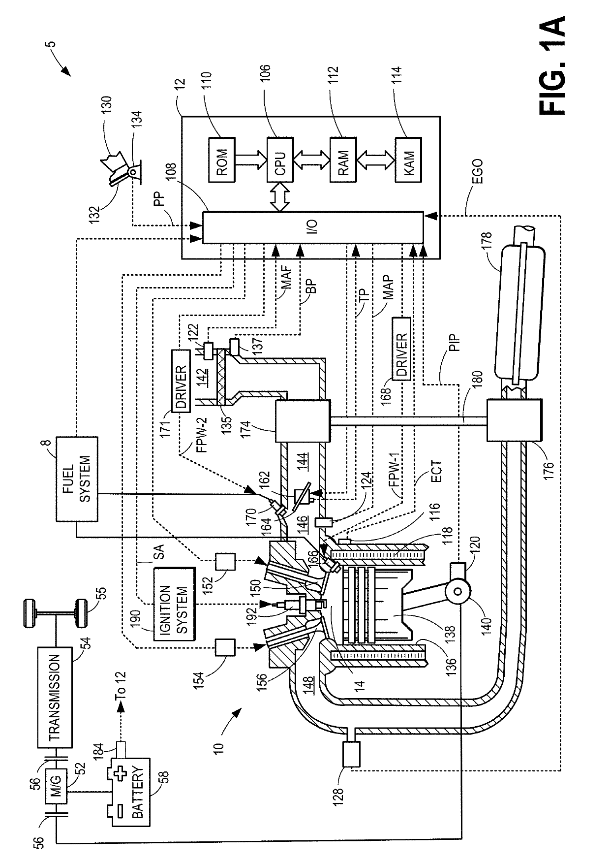
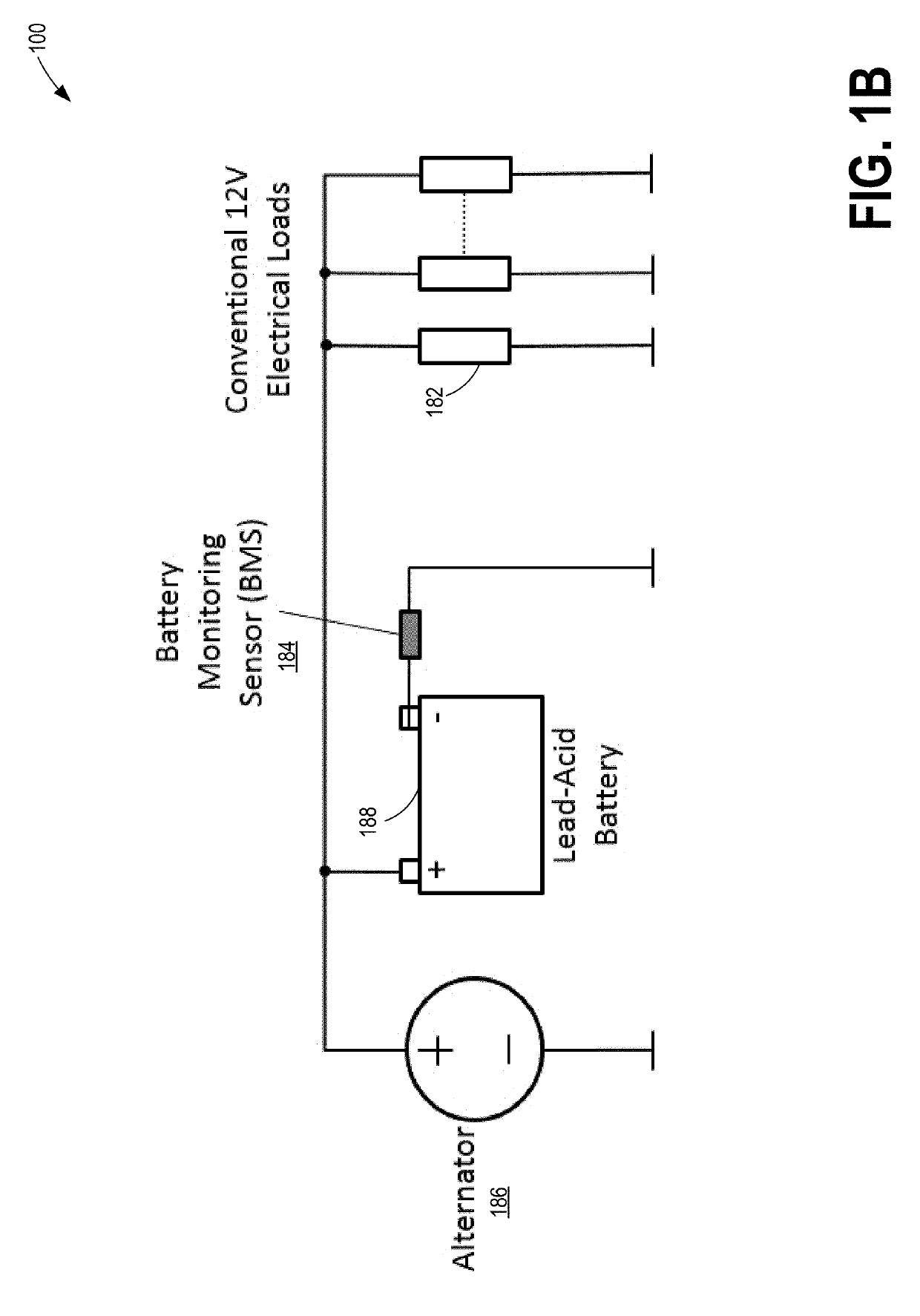
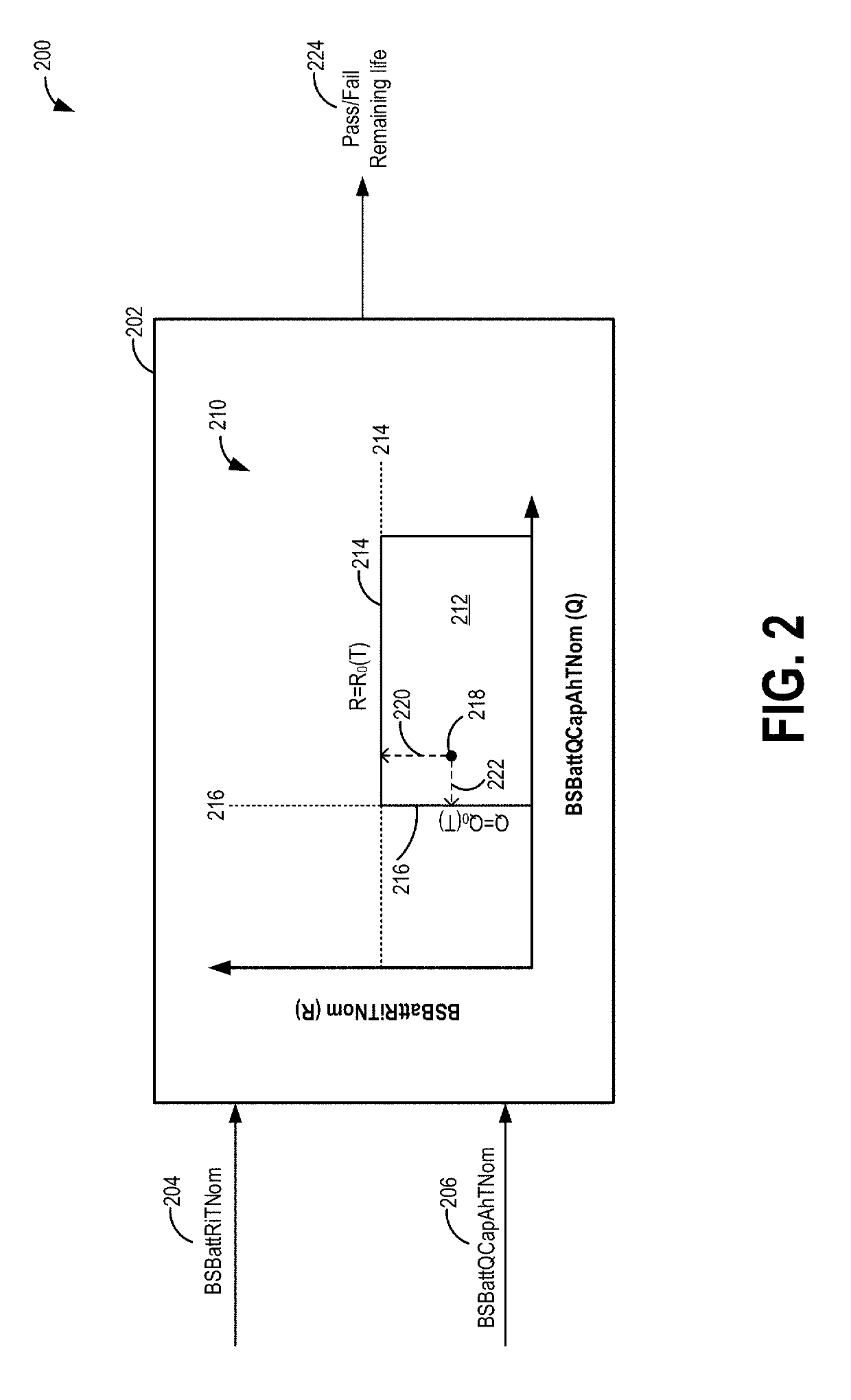
[0027]The following description relates to systems and methods for predicting the remaining life of a battery of a vehicle system, such as the example vehicle system of FIG. 1A including the battery architecture of FIG. 1B. An on-board controller may be configured perform a control routine, such as the example routines of FIGS. 3-4, to use statistical and measured data to predict the remaining life of a vehicle battery. The controller may compare estimated battery characteristics to corresponding thresholds, as shown at FIG. 2. Further, the controller may estimate a speed of convergence of the estimated battery characteristic to the corresponding threshold, as shown at FIG. 6, to predict the end of life of the battery. The thresholds may be calibrated based on data received from the given vehicle as well as other vehicle data, as explained at FIGS. 5, 7, 10, and 12. In addition, multiple intermediate thresholds preceding the EOL may be selected. Various notifications may be sent and...


PUM


Abstract

Methods and systems are provided for reliably providing a prognosis of the life-expectancy of a vehicle battery. A state of degradation of the battery is predicted based on a rate of convergence of a metric, that is derived from a sensed vehicle operating parameter, towards a defined threshold, determined based on past history of the metric. The predicted state of degradation is then converted into an estimate of time or distance remaining before the component needs to serviced, and displayed to the vehicle operator. Vehicle control and communication strategies may be defined with respect to the predicted state of degradation.

Description

FIELD[0001]The present application relates to methods performed in conventional motor vehicles, hybrid vehicles, and electric vehicles for estimating the remaining life of a battery that is commonly implemented to start the vehicle and support electrical loads when the ignition is turned off. Such a battery is commonly referred to as a Starting-Lighting-And-Ignition-Battery (or SLI-Battery) in the literature. The basic method described herein may also be applied to propulsion batteries used in hybridized or electric vehicles based on Li-Ion or other technologies.BACKGROUND AND SUMMARY[0002]Vehicle engines include an energy storage device, such as a lead-acid battery, for powering a starter motor as well as to support electrical load transients. Such a battery is commonly referred to as an SLI-battery in the literature. A propulsion battery may also be included in a hybrid electric vehicle to power an electric motor coupled to the driveline. Batteries degrade over time and have to be...

Claims


Application Information

Patent Timeline
IPC IPC(8): B60L11/18G01R31/36B60L3/00G07C5/08
CPCG07C5/0841B60L3/0061G07C5/0808B60L58/12G01R31/392B60L58/16G01R31/382G07C5/0825B60L3/0046B60L1/003B60L3/12B60L50/16B60L50/60B60L58/20B60L2250/16B60L2240/44B60L2260/50Y02T90/16Y02T10/7072Y02T10/70
Inventor KUMAR, PANKAJMAKKI, IMAD HASSANLANDOLSI, FAKHREDDINEEIFERT, MARKMALEKPOUR, SHEIDALINDEN, DAVID W.
Owner FORD GLOBAL TECH LLC
Learn More