Spring sleeve, cylinder, piston cylinder unit and method of manufacturing a piston cylinder unit

a piston cylinder and spring sleeve technology, which is applied in the direction of wound springs, shock absorbers, other domestic articles, etc., can solve the problems of increasing the friction and wear between the spring and the friction partner, increasing the cost and the risk of “buckling” and inelastic deformation of the coil spring, so as to achieve the effect of improving the movement characteristics and facilitating the reduction of the piston cylinder uni

Inactive Publication Date: 2019-06-13
STABILUS
View PDF0 Cites 1 Cited by
  • Summary
  • Abstract
  • Description
  • Claims
  • Application Information

AI Technical Summary

Benefits of technology

[0008]An aspect relates to a low-cost spring sleeve for a piston cylinder unit, a cylinder for a piston cylinder unit, a piston cylinder unit and a manufacturing method of manufacturing such a piston cylinder unit, which facilitates reduced wear and improved movement characteristics of a piston cylinder unit.

Problems solved by technology

At the same time, however, a greater tolerance also increases the risk of “buckling” and inelastic deformation of the coil spring, due to which undesirable noises and / or damage to the cylinder or the spring sleeves can be caused.
However, the aforesaid solution has the disadvantage that it regularly increases the friction and the wear between the spring and the friction partners.
Added to this is the fact that the coated spring is difficult to manufacture, and thus significantly increases the costs of the piston cylinder unit.
Another problem of the known piston cylinder units is that, when using a lubricant between spring and friction partners to reduce the wear, the noise generated and the risk of seizing, a displacement or accumulation of the lubricant can occur due to a stroke movement, due to which the lubricating effect of the lubricant is limited.
On the other hand, this embodiment is more difficult to manufacture and in particular injection molding with grooves of varying depth in a sleeve inner surface in one piece is scarcely possible, due to which the manufacturing costs increase.
In particular, trials have revealed that a share of approximately 20% of polytetrafluoroethylene leads to especially low friction over the entire product service life.
On the other hand, this embodiment is more difficult to manufacture, in particular by injection molding in one piece of a cylinder with grooves of varying depth on a cylinder outer surface, due to which the manufacturing costs increase.
On the other hand, this embodiment is more difficult to manufacture, and in particular injection molding in one piece is scarcely possible, due to which the manufacturing costs increase.
However, it is difficult to introduce such grooves into the inner surface of the spring sleeve(s).
An introduction of grooves of variable depth into the inner surface of the sleeves is difficult, in particular if the sleeves are to be manufactured in one piece.

Method used


Image

  • Spring sleeve, cylinder, piston cylinder unit and method of manufacturing a piston cylinder unit
  • Spring sleeve, cylinder, piston cylinder unit and method of manufacturing a piston cylinder unit
  • Spring sleeve, cylinder, piston cylinder unit and method of manufacturing a piston cylinder unit

Examples


Embodiment Construction

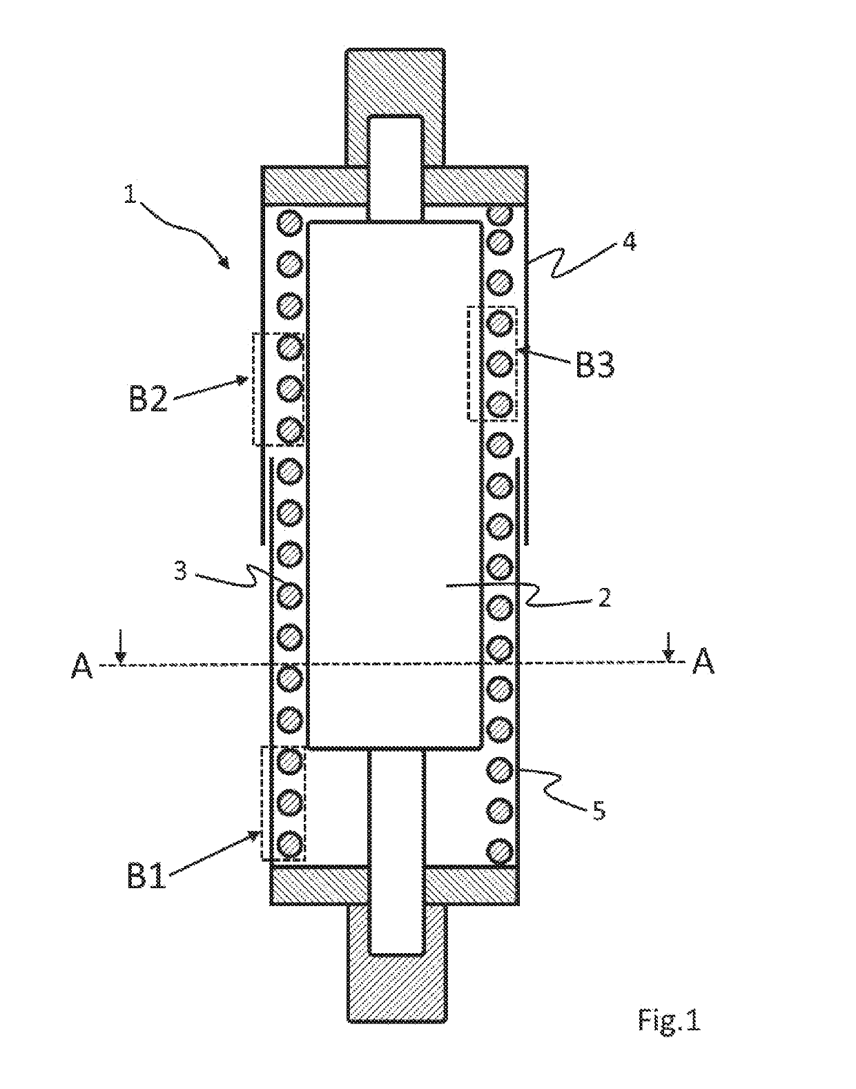
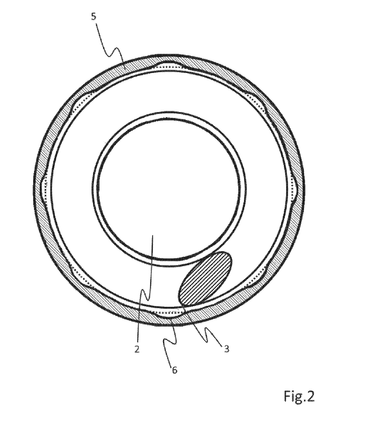
[0075]FIG. 1 shows a schematic sectional view of a piston cylinder unit 1 according to embodiments of the invention, comprising a cylinder 2, a spring 3, an outer spring sleeve 4 and an inner spring sleeve 5. The two spring sleeves 4, 5 are arranged concentrically around the centrally arranged cylinder 2. The spring 3 is supported and guided between the two spring sleeves 4, 5 partially engaging in one another and the cylinder 2. The outer spring sleeve 4 has a larger inner diameter than the outer diameter of the inner spring sleeve 5, due to which the inner spring sleeve 5 can penetrate further into the outer spring sleeve 4 in the event of loading of the piston cylinder unit 1.

[0076]In the inside of the cylinder 2, there can be arranged, for example, a gas pressure spring, or the cylinder 2 can be part of a gas pressure spring. The cylinder 2 can also consist of several cylinder segments, which can partially penetrate into one another, in order to shorten or lengthen the cylinder ...


PUM

PropertyMeasurementUnit
depthaaaaaaaaaa
diameteraaaaaaaaaa
elasticaaaaaaaaaa

Abstract

Provided is a spring sleeve for a piston cylinder unit, wherein the spring sleeve is adapted to receive a spring, at least partially, and to guide it, wherein the spring sleeve has a cylindrical sleeve inner surface. The embodiment further relates to a cylinder for a piston cylinder unit, wherein the cylinder) is adapted to be arranged inside a spring of a piston cylinder unit. The embodiment also relates to a piston cylinder unit, including a cylinder, a spring arranged concentrically around the cylinder, and an inner spring sleeve and outer spring sleeve each arranged concentrically around the spring, wherein the cylinder and the spring are arranged inside the inner spring sleeve and the outer spring sleeve. Finally, the embodiment relates to a method of manufacturing such a piston cylinder unit.

Description

CROSS-REFERENCE TO RELATED APPLICATION[0001]This application claims priority to German Application No. 10 2017 129 539.9, having a filing date of Dec. 12, 2017, the entire contents of which are hereby incorporated by referenceFIELD OF TECHNOLOGY[0002]The following relates to a spring sleeve for a piston cylinder unit, wherein the spring sleeve is adapted to receive a spring, at least partially, and guide it along a stroke path of the piston cylinder unit, wherein the spring sleeve has a cylindrical sleeve inner surface. The following further relates to a cylinder for a piston cylinder unit, wherein the cylinder is adapted to be arranged inside a spring of a piston cylinder unit. The following also relates to a piston cylinder unit, comprising a cylinder, a spring arranged concentrically around the cylinder, and an inner spring sleeve and outer spring sleeve each arranged concentrically around the spring, wherein the cylinder and the spring are arranged inside the inner spring sleeve...

Claims


Application Information

Patent Timeline
Patent Type & Authority Applications(United States)
IPC IPC(8): F16F9/38F16F1/02F16F9/32F16F13/00C08G69/00C08L77/00C08K7/06C08K3/04C08K7/14C08K3/40
CPCF16F9/38F16F1/024F16F9/3235F16F13/007F16F9/3278C08G69/00C08L77/00C08K7/06C08K3/04C08K7/14C08K3/40F16F2224/0241F16F2226/04F16F13/002F16F2226/02F16F2230/0023F16F2230/0058F16F2230/04F16F2230/10B29D23/00B29K2077/00C08L2205/16F16F1/12F16F9/0281F16F1/128F16F2226/026F16F1/122
Inventor SCHNEIDER, MICHAEL
Owner STABILUS
Why Eureka
Try Eureka