Supercharge Your Innovation With Domain-Expert AI Agents!

Multi-z confocal imaging system

a confocal imaging and multi-z technology, applied in the field of 3d confocal imaging systems, can solve the problems of unacceptably slow 3d imaging rate, confocal microscopy, and inability to achieve fast image contrast, improve image contrast and snr, and increase the axial resolution of the z axis

Active Publication Date: 2019-06-13
TRUSTEES OF BOSTON UNIV
View PDF12 Cites 0 Cited by
  • Summary
  • Abstract
  • Description
  • Claims
  • Application Information

AI Technical Summary

Benefits of technology

The present invention is about a new technology for fast and efficient detection and imaging of multiple planes in a sample. The technology uses a novel detector system that splits the detected signal into multiple signals corresponding to different depths in the sample without significant signal loss. The detector system includes two or more reflecting pinholes that send the conjugate image to a detector, such as a photodiode. The reflecting pinholes are arranged so as to define probe volumes that fully span the illumination line focused in the sample. The Multi-Z confocal microscope can use a series of reflecting pinholes to capture and image successively shallower probe volumes, minimizing signal loss. The detected signal can be split into multiple signals through the use of a novel detector system. The systems provide fast imaging over exceptionally large volumes and are flexible and scalable. The technology is relatively simple to implement and can work with both fluorescence and non-fluorescence contrast configurations.

Problems solved by technology

One disadvantage of confocal microscopy is that it is slow, since images must be constructed point by point.
While this is often adequate for 2D imaging, it may be unacceptably slow for 3D imaging, since 3D volumetric imaging requires additional scanning in the axial dimension.
For biological imaging, this rate is often too slow.
Such a construction would be contrary to that used in a conventional confocal microscope where the goal is to obtain as tight a focus as possible of the illumination point and would result in poor axial resolution.
In comparison, for example, consider two-photon microscopy is inherently a high-resolution device, and does not allow such flexibility.

Method used


Image

  • Multi-z confocal imaging system
  • Multi-z confocal imaging system
  • Multi-z confocal imaging system

Examples


Embodiment Construction

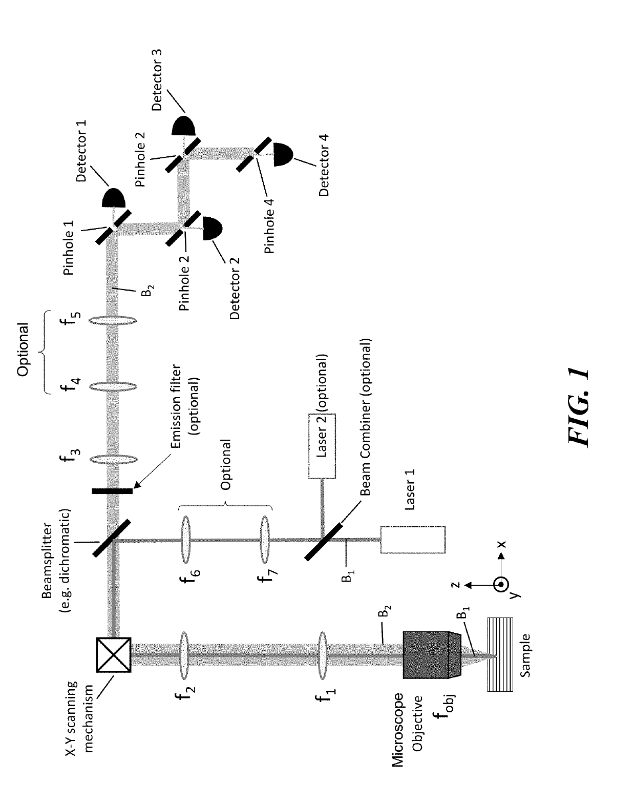
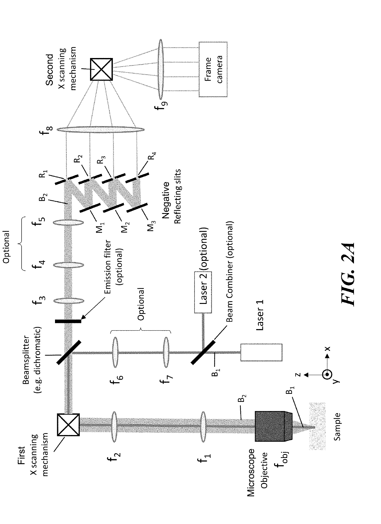
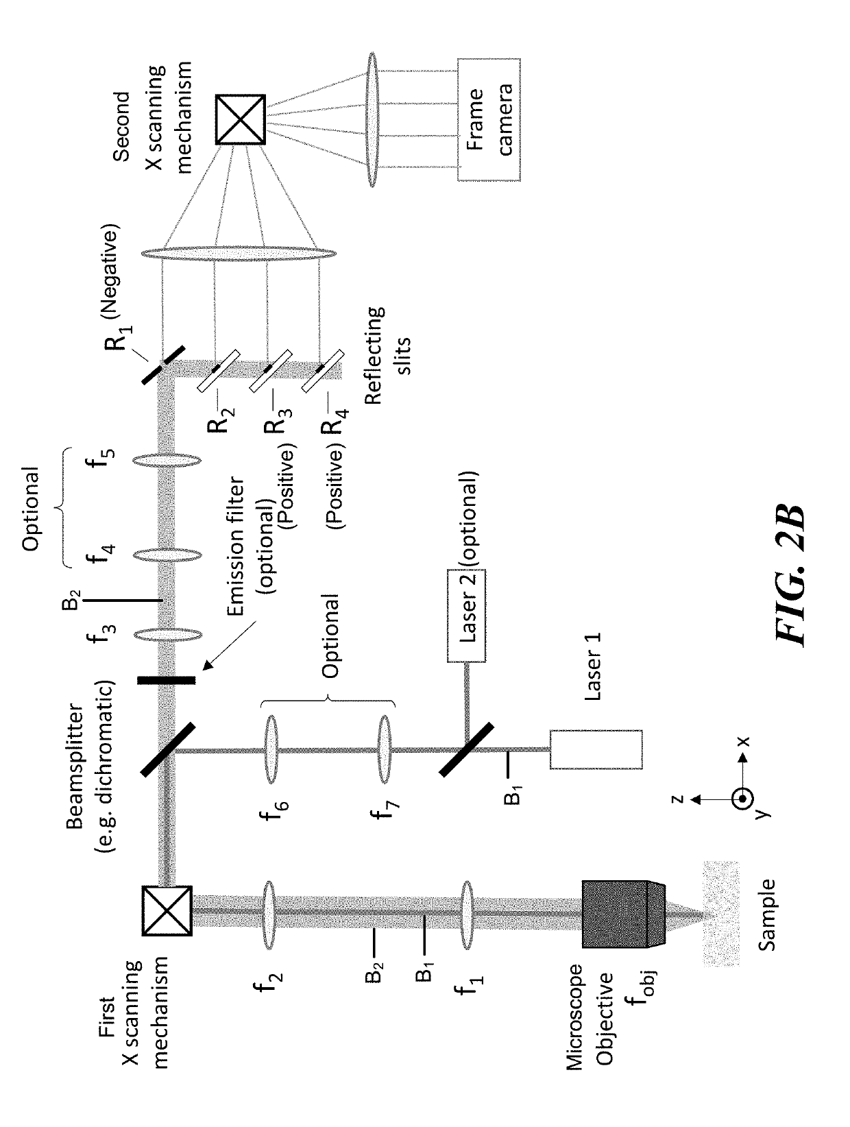
[0037]The present invention is directed to a Multi-Z confocal microscopy system that can image multiple depths into a sample simultaneously. The system includes one or more illumination sources, such as a LASER light source that forms an illumination beam. In accordance with some embodiments of the invention, the system forms an illumination beam that under fills the microscope objective and is focused to an illumination line that extents in the Z dimension (or a sheet or window extending the Z and X or Z and Y dimensions). In accordance with some embodiments of the invention, the system includes an array of reflecting pinholes (e.g., positive or negative reflecting pinholes or a combination thereof) that can be arranged and configured to image the different depths into the sample that were illuminated by the illumination line extending in the Z dimension. In accordance with some embodiments of the invention, the system can further include an X and / or Y scanning mechanism that is co...


PUM


Abstract

A Multi-Z confocal microscopy system can simultaneously record from multiple Z-sections, and thus performs high speed volumetric imaging. An illumination line can be formed by under-filling the illumination beam in the aperture of the microscope objective. The illumination line extends in the Z dimension into the target sample to be imaged and an X-Y scanning mechanism can be used to scan the illumination line over the sample. The detection signal emanating from the scanned sample can be collected through the full numerical aperture of the microscope objective and directed to a detector subsystem. The detector subsystem includes an array of reflecting pinhole detectors and each reflecting pinhole detector is configured to image a volume at a different depth in the sample. This configuration enables reflecting pinhole detector array to image more than one depth volume at the same time.

Description

CROSS-REFERENCE TO RELATED APPLICATIONS[0001]This application claims any and all benefits as provided by law including benefit under 35 U.S.C. § 119(e) of the U.S. Provisional Application No. 62 / 597,638, filed Dec. 12, 2017 and No. 62 / 608,058, filed Dec. 20, 2017, the contents of both of which are incorporated herein by reference in their entirety.STATEMENT REGARDING FEDERALLY SPONSORED RESEARCH[0002]This invention was made with government support under grant no. R21EY027549 awarded by the National Institute of Health. The government has certain rights in the invention.REFERENCE TO MICROFICHE APPENDIX[0003]Not ApplicableBACKGROUNDTechnical Field of the Invention[0004]The present invention relates to 3 dimensional confocal imaging systems and more specifically, to a confocal microscope that can simultaneously generate images of multiple Z sections of a sample.Description of the Prior Art[0005]Confocal microscopy is generally based on a principle of point scanning wherein a beam of li...

Claims


Application Information

Patent Timeline
Patent Type & Authority Applications(United States)
IPC IPC(8): G02B21/00G02B27/09G02B5/08G02B27/10
CPCG02B21/0052G02B21/0032G02B27/0977G02B5/08G02B27/10G02B21/004G02B21/0048G02B21/006G02B27/145
Inventor MERTZ, JEROMEBADON, AMAURYWEBER, TIMOTHYXIAO, SHENGTSANG MIN CHING, JEAN-MARC
Owner TRUSTEES OF BOSTON UNIV
Features
  • R&D
  • Intellectual Property
  • Life Sciences
  • Materials
  • Tech Scout
  • Unparalleled Data Quality
  • Higher Quality Content
  • 60% Fewer Hallucinations
Learn More