
Modular trailer system

Active Publication Date: 2019-06-20
HALDEX BRAKE PROD CORP
View PDF0 Cites 2 Cited by
  • Summary
  • Abstract
  • Description
  • Claims
  • Application Information

AI Technical Summary

Benefits of technology

The patent describes a trailer brake and monitoring system that can be easily mounted to a trailer and replaced if needed. The system includes a control module that can communicate with auxiliary components to transmit data wirelessly to a central server. The control module also has a CAN port that allows for faster data rates. In addition, the system can turn on ABS warning lamps, resolve issues with viewing dolly ABS warning lamps, and broadcast system status over the network. The technical effects of this invention are improved functionality and reliability of the trailer brake and monitoring system.

Problems solved by technology

A loss of compressed air in typical air brake systems means that the power spring applies a braking force to prevent the vehicle from moving.
While this configuration will provide a functioning system in the event of catastrophic failure of the service / control line, this system will not provide information to the driver regarding the efficiency of the braking system.
For example, the service / control line may suffer from a leaky connection causing substantial leaking of the compressed air.
There may be enough air pressure in the system to allow for operation of the vehicle, but the vehicle may suffer from brake drag, meaning the air pressure is not high enough to completely overcome the power spring such that the brake is partially applied during normal driving operation.
Many problems relating to the air supply to both the service and emergency systems occur with prior art systems.
For example, with current systems, the emergency / supply line extends to the braking mechanism adjacent to the wheel, and is therefore, subject to damage.
If the emergency / supply line becomes damaged, there is no way to determine this if the service / control line continues to function, even if it is only partially functional.
Likewise, incorrect connection of supply hoses when a braking system is removed for servicing and re-installed may occur.
If, for example, the emergency / supply line is incorrectly re-installed, upon failure of the primary supply line, the braking system will not function.
Another air related problem that exists for prior art systems is the provision of service / control air pressure to the trailer when the brakes are not applied.
If, for example, there is an air leak from the tractor to the trailer on the service / control pressure line at all times. Still another problem that prior art systems face is the service / control and emergency / supply lines can deliver inadequate pressure due to obstructions or leaks within the air lines.
If, for example, moisture in a pressure line freezes and obscures the air pressure line or an air line cracks or gets damaged by road debris.
Another problem that prior art systems face is the provision of stoplight power to the trailer when the brakes are applied.
Additional problems with prior art systems include the lack of input data to the brake monitor.
For example, prior art systems do not provide wheel speed data on the power line from a faulty Anti-Lock Braking System (ABS) controller.
If, for example, the ABS controller has failed or the wheel speed sensors are faulty or have an excessive gap with the exciter ring, then the ABS ECU cannot detect or transmit individual wheel speeds.
Similarly, incorrect connection of the 7-conductor electrical connection to the towed vehicle leads to problems in prior art systems.
Still another problem that prior art systems face is incorrect air connections to the dolly that connects two trailers together.
Incorrect connection of service / control or emergency / supply hoses will cause a various number of failure conditions.
Likewise, another problem that prior art systems face is incorrect connection of supply hoses when a braking system is removed for servicing and re-installed.
If, for example, the emergency / supply line is incorrectly re-installed, upon failure of the primary supply line, the braking system will not function.
Another problem that prior art systems face is the service / control and emergency / supply line glad-hand shut-off valves at the rear of the trailer.
If, for example, the service line glad-hand shut-off valve is shut off to the towed vehicle causing a failure of the service / control line, the service braking system will not function.
A loss of electrical power may cause these systems to be non-functional, which would generally be apparent.
However, in a situation with reduced or relatively lower power, the systems may not be completely prevented from functioning, but system function and operation may be substantially impaired.
Further, conventional trailer brake control systems do not include a modular design (e.g., allowing the system to be quickly removed and replaced upon failure to keep the vehicle in operation), the ability to handle a 4S (“sensor”) / 3M (“modulator”) configuration with a single trailer control module, a controller area network port allowing the system to transmit data to, and receive data from, other components in a high-speed manner, and a brake monitoring system (e.g., a system that monitors pressure in service and emergency brake pressure lines) that is integrated in a trailer control module with a wheel speed monitoring and ABS control system.

Method used


Image

  • Modular trailer system
  • Modular trailer system
  • Modular trailer system

Examples


Embodiment Construction

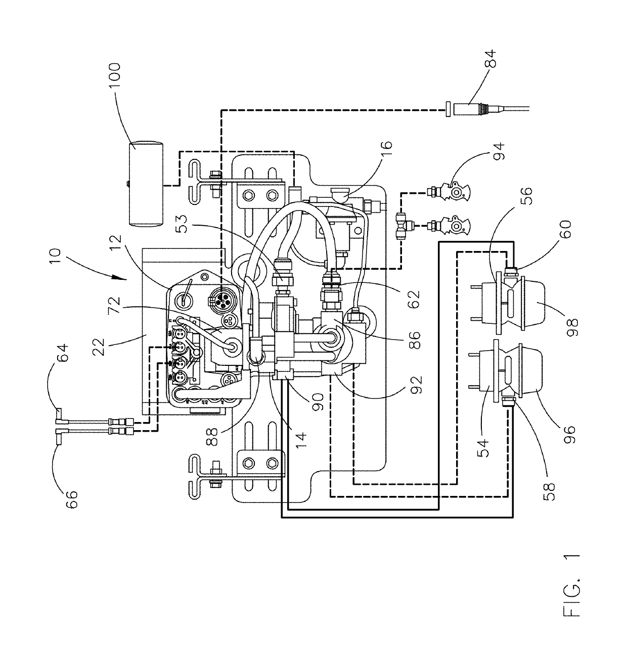
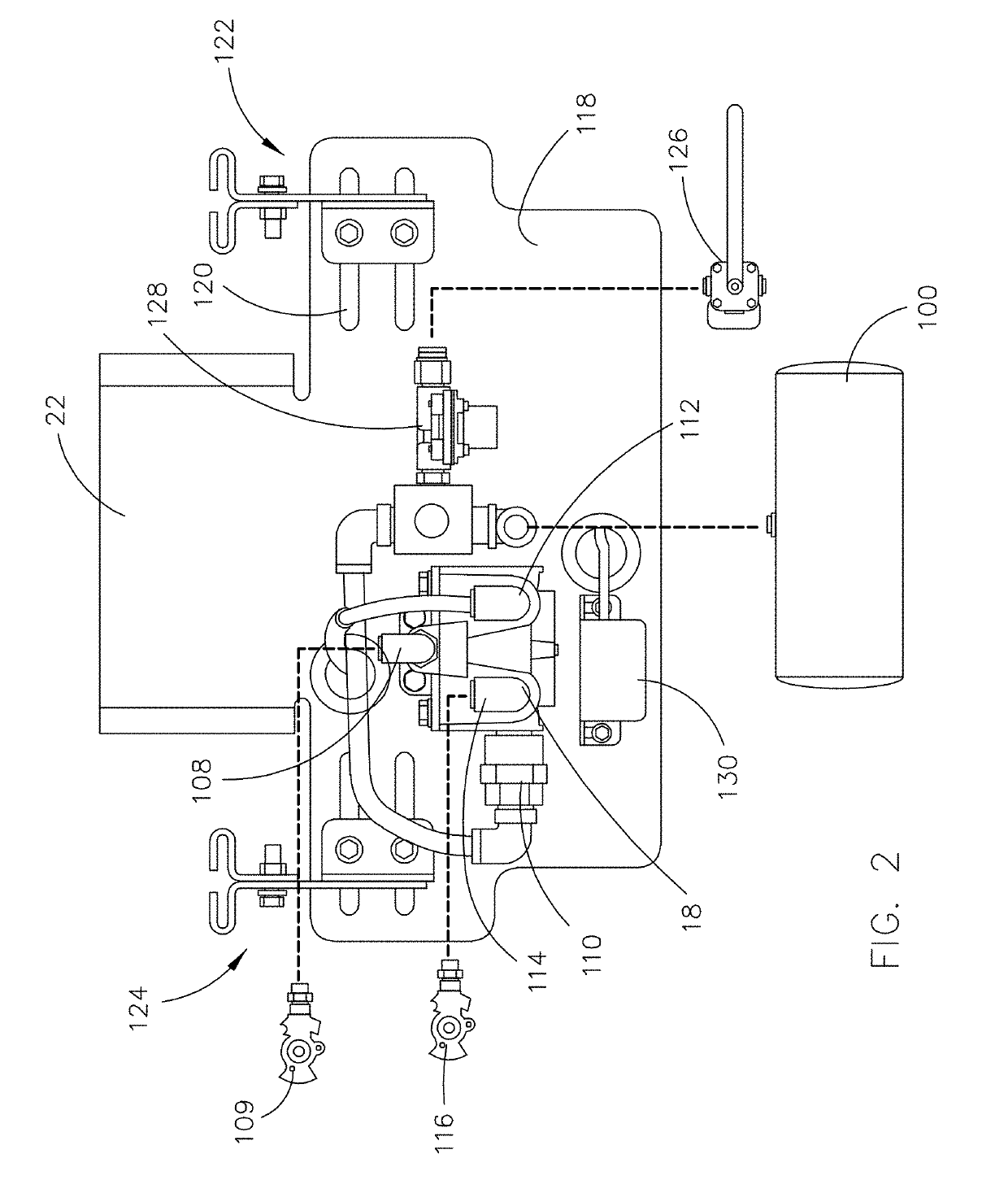
[0041]A trailer brake and monitoring system in accordance with one embodiment of the invention described herein is identified generally with the reference numeral 10 in FIG. 1. The trailer brake and monitoring system includes a trailer control module 12, a brake valve 14, a reservoir purge valve 16, a booster valve 18 (FIG. 2), a communications device 20 (FIG. 4), and a mounting bracket 22 to which the trailer control module 12, brake valve 14, reservoir purge valve 16, and booster valve 18 are mounted.

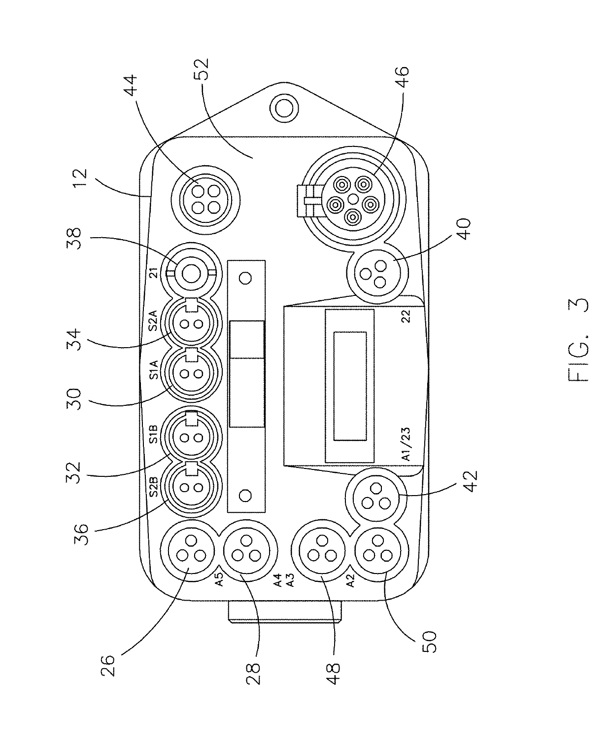
[0042]Referring to FIG. 6, the trailer control module 12 includes a processor 24 that is electrically coupled with, configured to receive data or instructions from, and configured to transmit data or instructions to: a brake supply pressure input 26, a brake control pressure input 28, a first wheel speed input 30, a second wheel speed input 32, a third wheel speed input 34, a fourth wheel speed input 36, a first valve output 38, a second valve output 40, a third valve output 42, a con...


PUM


Abstract

A trailer brake and monitoring system with a trailer control module, which has a processor, a signal input, a first wheel speed input, a second wheel speed input, a valve output, and a data port. The processor receives a signal from the signal input, and the processor sends the signal to the data port. The processor receives a first wheel speed signal from the first wheel speed input and a second wheel speed signal from the second wheel speed input. The processor is configured to send a first brake signal to the valve output based on at least one of the first wheel speed signal and the second wheel speed signal. The trailer control module may include third and fourth wheel speed inputs and a second valve output. The data port may be a power input configured for connection with a PLC cable and / or a CAN port.

Description

CROSS-REFERENCE TO RELATED APPLICATIONS[0001]This application is based on and claims priority to U.S. Provisional Application Ser. No. 62 / 608,229, filed on Dec. 20, 2017 and titled Modular Trailer System, which is incorporated herein by reference in its entirety.STATEMENT REGARDING FEDERALLY SPONSORED RESEARCH OR DEVELOPMENT[0002]Not applicable.STATEMENT REGARDING JOINT RESEARCH AGREEMENT[0003]Not applicable.BACKGROUND OF THE INVENTION1. Field of the Invention[0004]The present application relates generally to a modular trailer system and, in particular, to a trailer brake and monitoring system.2. Description of Related Art[0005]Air operated braking systems have long been utilized to control commercial vehicles such as trucks and trailers, which typically have large gross vehicle weights, in a safe and effective manner. The considerable inertial mass of these heavy-duty vehicles, in combination with the high speeds at which they travel, requires a braking system which responds rapidl...

Claims


Application Information

Patent Timeline
IPC IPC(8): B60T7/20B60T8/17B60T13/68B60T13/66B60T17/22
CPCB60T7/20B60T8/1708B60T13/683B60T13/662B60T17/22B60D1/64B60L2200/28B60R2021/0104B60R2021/01259B60T2270/406
Inventor WILLIAMS, JUSTIN
Owner HALDEX BRAKE PROD CORP
Learn More