
Machine Monitoring

a technology of machine monitoring and monitoring device, which is applied in the direction of testing/monitoring control system, electric controller, instruments, etc., can solve the problems of affecting the performance of the machine,

Inactive Publication Date: 2019-06-20
WEIR MINERALS AUSTRALIA LTD
View PDF0 Cites 13 Cited by
  • Summary
  • Abstract
  • Description
  • Claims
  • Application Information

AI Technical Summary

Benefits of technology

The patent text describes a method for controlling operating parameters of a machine to reduce the impact of identified components on its health level. This helps to prevent machine failure and downtime. The method can also be used to control the replacement criterion of a component, reducing the cost and time of maintenance. The identification of components takes into account their predicted deterioration time, which helps to avoid unexpected failures. Overall, the method improves the efficiency and lifespan of machines while reducing maintenance costs.

Problems solved by technology

Often such machinery operates in highly destructive conditions, whereby components of the machines may be worn away or pitted due to repetitive material impact.
The degradation of one component can lead to imbalances in the machine that result in degradation of further components.
Both performance and life of a machine can have a direct impact on the costs of running an operation.
If a machine fails it can result in the shutdown of an entire process.
Similarly, machines running at sub-optimal performance levels can result in an inefficient process that consumes more energy than required.
Such a method of monitoring machines relies on the operator's experience, and may ignore many operating parameters of a machine that are not readily available for measurement by the operator.
This may lead to inaccuracies in the estimates made by the operator.
For example, this may be at the expense of the overall efficiency or performance of a machine.
The method may reduce the time and cost of maintaining equipment, and may reduce downtime of machines caused by unexpected component failure or wear.

Method used


Image

  • Machine Monitoring
  • Machine Monitoring
  • Machine Monitoring

Examples


Embodiment Construction

[0074]In the following detailed description, reference is made to accompanying drawings which form a part of the detailed description. The illustrative embodiments described in the detailed description, depicted in the drawings and defined in the claims, are not intended to be limiting. Other embodiments may be utilised and other changes may be made without departing from the spirit or scope of the subject matter presented. It will be readily understood that the aspects of the present disclosure, as generally described herein and illustrated in the drawings can be arranged, substituted, combined, separated and designed in a wide variety of different configurations, all of which are contemplated in this disclosure.

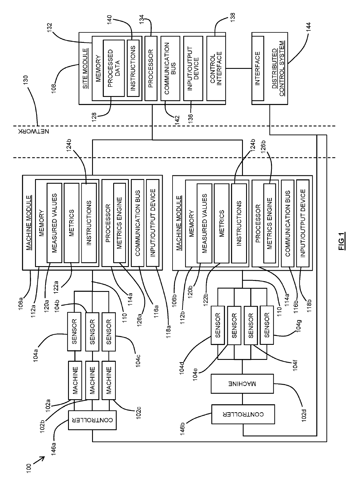
[0075]Referring firstly to FIG. 1, the system 100 broadly comprises a plurality of machines 102, a plurality of corresponding sensors 104, first and second machine modules 106, and a site module 108. To facilitate an understanding of the system, it will henceforth be descri...


PUM


Abstract

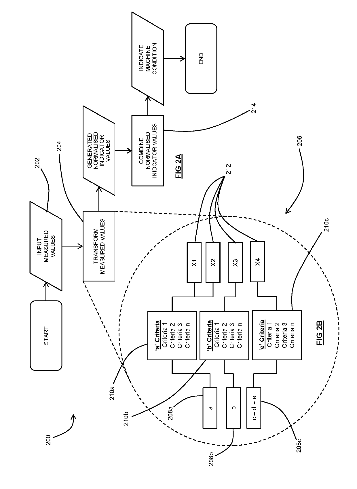
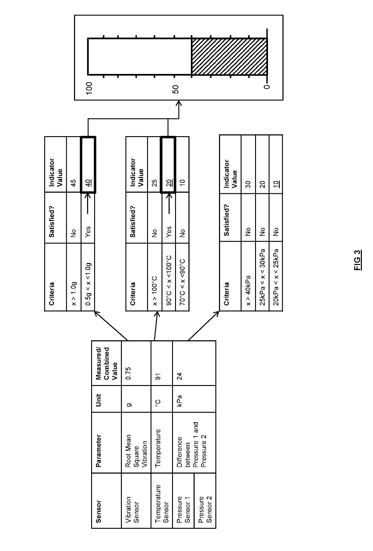
Disclosed is a method for monitoring the operation of a machine. The method comprises measuring a plurality of parameters of the machine to obtain a plurality of measured values and transforming the measured values to generate a plurality of normalised indicator values. The method further comprises using the normalised indicator values to indicate a condition of the machine. Also disclosed is a method of managing the operation of a machine. The method includes measuring a plurality of parameters of the machine, predicting, based on historical data, a time at which the measured values will reach a replacement criterion, identifying one or more components of the machine that require to be replaced in order to prevent the replacement criterion being met, and communicating, to a service provider, an indication of the one or more components that require replacement.

Description

TECHNICAL FIELD[0001]This disclosure relates to a method of monitoring a machine. The method finds particular, but not exclusive, use in industrial processing operations, such as in the minerals, power and mining industries.BACKGROUND ART[0002]Machinery used in various operations, such as minerals processing, chemical, oil and gas, power generation etc. experience constant changes in their condition. This may be in the form of e.g. fluctuations in performance and / or degradation of various components of the machinery.[0003]In regards to performance fluctuations, these may be caused by internal changes to the machine or external (e.g. environmental) changes. Such changes may require modification of various operating parameters of the machine to ensure that the performance of the machine is maintained within a suitable range. For example, a change in the consistency of material being processed by a hydrocyclone may require an adjustment of the inlet flow rate of the hydrocyclone.[0004]...

Claims


Application Information

Patent Timeline
Patent Type & Authority Applications(United States)
IPC IPC(8): G05B23/02G05B11/01G05B13/02G16B45/00
CPCG05B23/0283G05B23/0235G05B23/0221G05B23/0272G05B11/01G05B13/026G05B15/02G05B13/02G07C3/00G01D3/022G01N19/08G01D3/02G07C3/06
Inventor STRUDWICKE, CRAIG DONALDHAMBE, MICHAELJANOS, MARKBAKER, BENJAMIN MICHAEL
Owner WEIR MINERALS AUSTRALIA LTD
Learn More