In the worst case, this can cause a
control point phase to flip from phase to anti-phase.
This creates localized cancellation of the wave that increases the
noise floor by causing sudden changes in the field, on top of potentially “stalling” transducers by forcing them to immediately try to vibrate in way that is diametrically opposed to their current vibration.
Physical transducers tend to have a
narrowband response, meaning that the transducers become less efficient as this frequency moves away from the carrier frequency.
Therefore, fast changes in the phase of the
transducer, which are implied by fast changes in the phase of a
control point, produce inefficiency.
Discontinuous jumps in the phase of control points can generate spurious detections in a
system modified to detect sharp phase changes for tracking purposes.
However, as both the frequency of updates increases and the
system size increases to a point at which the assumptions that the differences in
travel time of the
waves is insignificant fails, the predictions of such techniques become less accurate.
Worse, in cases where the control points are moving, the measurement of time-weighted averages of acoustic quantities in a region of space may be completely misleading.
This approach has other limitations such as only supporting simple 3D shapes and surfaces.
Unfortunately, if a
phased array is updated through time, this is also a flaw.
The
wave speed can be fundamentally too slow for
waves created at the same time in different spatial positions on the array or arrays to appreciably reach the same
control point at the same time.
This, in quickly updating or wide
aperture array configurations will cause differences in
time of arrival, causing the waveform created at the control point to be smoothed out in time and smeared in space.
If the array is small enough in space to be traversed quickly by a wave or the updates slow through time compared to the
wave speed, the deleterious effects of these
travel time differences can be so small as to be unnoticeable.
Traditional parametric audio suffers from the fact that it is a vibration emitted from a wide flat surface with no change in phase or
signal delay across the surface of the speaker.
The result is that each channel of audio produced unintentionally encodes phase information that may distort its
perception, or worse reveal to the human that it was emitted from a surface and not the intended object in the recreated audio scene.
Further, producing multiple independent fields from many phased acoustic transducers represents a difficult
computational problem.
While these phases have similar angular differences between elements, they may cause the collective phase of the transducers to experience extra drift over time.
While this achieves the correct result, it may not be an
ideal solution since it involves a summation over all
transducer activation coefficients.
For the reasons described earlier, this is undesirable.
This moves each time-step in angle by the maximum amount and so is limited in speed.
As each device would be ideally unaware of the physical
layout of the other devices, the eigensystem would obtain different sets of optimal phases and so these various devices would find themselves unable to contribute to a shared acoustic field.
There are a small number of worst cases that the eigensystem by nature avoids that this approach, used alone, would find problematic.
If two control points are one-quarter of a
wavelength apart then it is not possible for them to be π apart in
phase angle as that would necessitate a change in frequency.
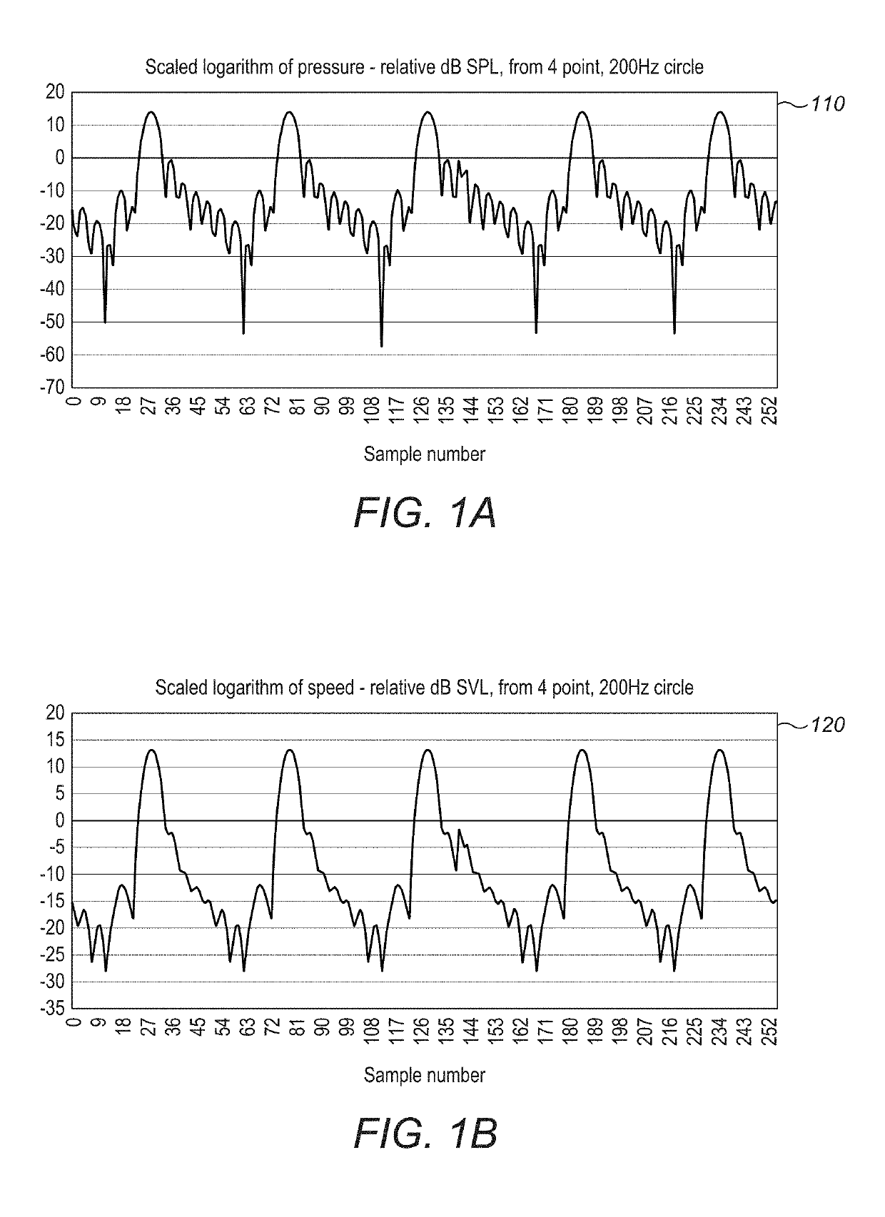
Both are difficult to measure even with specialized equipment because they involve measuring particle motions which are in general very small (the root-mean-squared particle displacement at 40 kHz is 199 nanometers at 120 dB).
Given the access
simulation does not dictate which to use in the same way that physical measurement does, it is unclear which is the correct value to use, as most literature is based on the inaccurate but easy to measure SPL value.
However, due to the need for time histories to contain many sample points with up to eight (three complex velocity components and one complex pressure) individual recorded quantities in each sample, exporting the
time history is bandwidth intensive.
Nevertheless, the complex-valued portions of the cancellations involved in the
noise surrounding the control points in the
time history will likely either be coherent or small and noisy.
An environment containing many transducers and potentially multiple users may create a challenging problem for producing mid-air haptic feedback.
For instance, if the desired haptic is meant for a user's palm, which is facing down, transducers placed above the user will not be able to contribute to the palm control region (blocked by the top of the hand).
Another challenge in this environment is continually updating the relative positions and orientations between the transducers and users.
Since this is a highly computationally intensive procedure in that it is likely difficult or impossible to achieve an optimal result in bounded time, there are described herein a number of
heuristic approaches that may be used to construct close-to-optimal solutions in low-cost, real-time hardware systems that may be commercially exploitable.
A connected spline or other interpolant may be more complex to evaluate, but will be only required every so often, requiring less bandwidth to transmit and shared with other devices.
At high frequencies, however, this generates a great deal of data that may be prohibitive for some technologies, such as
wireless control, to evaluate.
On the other hand, taking the trajectory data too early implies too great a maximum distance for the
waves to travel and an unnecessarily
long latency, during which time the user may have insisted on alternative data.
If there are many points assigned to a trajectory, then the fidelity of the produced
signal in time becomes greater for this additional cost.
This results in a further
histogram that is skewed through time and space.
While each
transducer can, in this approach, only influence a given control point sampled from the trajectory once, the array or arrays can at different points in time influence the same control point multiple times. In such a situation, the control point phase choices at these different points in time must agree, or the waves used to create the control points would not be coherent on arrival and so interfere in an uncontrolled way.
This is unwanted and so there is a need to modify the
power iteration, the repeated computation of the Ritz-Rayleigh iteration, to account for the decided phases that can no longer be changed.
However, within the current state of the art, building a
system consisting of multiple phase accurate point sources is not possible.
If it could be done, it would be commercially important, since large, expensive and cumbersome speaker systems involving multiple elements could be replaced by a single parametric speaker.
A further source of error can be found in the relative transducer amplitudes themselves.
As each transducer is effectively generating a localized diverging wave of audible sound along its path to the focus, this results in undesirable variation in each wave as it travels through the focus, and thus variation in the
directivity of the phase accurate virtual
point source.
The approach described here modulates each
basis function along the temporal axis—the trade-off being that narrower modulations in time provide more precisely tuned the time-of-arrival from each
basis function, at the cost of fewer transducers that can be used and thus lower power available to the
basis function produced.
This system is not possible with audio speakers as the reconstruction of point sources is prevented in these cases by the
wavelength of the sound, without consideration of the
phase adjustment.
However, there is a further corollary, as these
sound sources do not have physical presence and can be moved and placed arbitrarily.
An environment containing many transducers and potentially multiple users can create a challenging problem for producing mid-air haptic feedback.
A system with multiple transducer arrays and multiple requested fields can become computationally challenging if every field is to be contributed to by every transducer in the system.
Also, in a room-scale situation, users can interfere with fields by shadowing the fields produced by some transducers and not others.
In the context of large numbers of arrays and many points, however, it is not always computationally efficient to consider every transducer and every acoustic field simultaneously.
While
safer, this could potentially cause a noticeable gap in the acoustic field.
For instance, if the desired haptic is meant for a user's palm, which is facing down, transducers placed above the user will not be able to contribute to the palm control region (blocked by the top of the hand).
Another challenge in this environment is continually updating the relative positions and orientations between the transducers and users.

