Electro hydraulic drive and control system

Active Publication Date: 2019-07-04
FLUTRON
View PDF11 Cites 0 Cited by
  • Summary
  • Abstract
  • Description
  • Claims
  • Application Information

AI Technical Summary

Benefits of technology

The present invention aims to provide a hydraulic drive and control system that can improve various important functions simultaneously, such as energy efficiency, safety, and productivity. The system should have low energy consumption and high performance, and it should be easy to operate and learn. The limited ability of operators to control the machine is also taken care of by the control system, allowing the operator to focus on what to do while the system automatically takes care of the rest. Overall, the invention aims to create a unified system that can achieve maximum efficiency and productivity while minimizing energy waste.

Problems solved by technology

Typical is also that machines own moving parts that the system is driving together with the load is heavy and often has a weight of about 20% of the maximum load weight.
Typical is also for some machine types that they often not is strong enough to move at all or as fast as controlled to do.
Position sensors can be limited to important, hard working actuators that are decisive for machine productivity.
One very problematic and important thing for a hydraulic drive system is that, if the sum of all controlled flows to actuators is bigger than maximum pump flow capacity, will the actuators that have the highest pressure need, be the first one to get less flow than what the operator wants.
The control is in that case not working and dangerous situations can be the result.
The problem is difficult to handle as braking gives forces that are increasing the risk for overturning unless braking start long before the critical point.

Method used


Image

  • Electro hydraulic drive and control system
  • Electro hydraulic drive and control system
  • Electro hydraulic drive and control system

Examples


Embodiment Construction

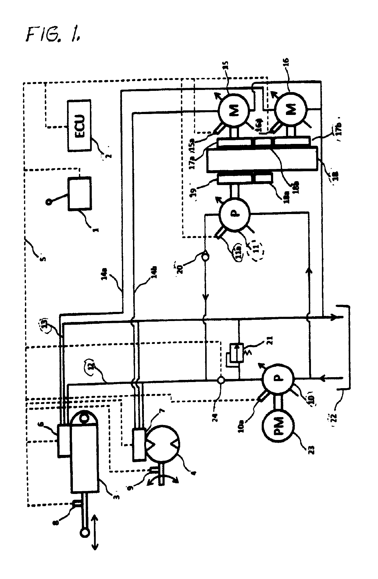
[0046]In the following description, an embodiment of the present invention is described with referents to a hydraulic drive and control system having an energy recovery system comprising a flywheel with a variable displacement pump, here named assisting recovering re-use the recovery pump, and two individual hydraulic rotating energy recovering motor connected there to.

[0047]FIG. 1 shows a hydraulic drive and control system according to an embodiment of the present invention. The system comprises an operator control unit (1) arranged with at least one shaft, steering wheel on the like to be operated by the operator, feeding in to the electronic control unit ECU (2).

[0048]A linear hydraulic cylinder actuator first type (3) with different size on pressurized areas on the piston and a second type hydraulic rotating actuator (4) are shown in the figure. A first position sensor (8) is arranged on the first actuator (3) to measure the position of the piston rod. A second position sensor (...


PUM


Abstract

A operator supporting electrohydraulic drive and control system based on, position sensors (8) (9), a electronic control unite ECU (2), a recovery, storing and re-use system for energy, and with actuator (3) (4) and the drive control valve (6) (7) bolted together in one (3+6) (4+7) unite and with the valve (6) (7) independently of the ECU (2) is controlling effective use of pump capacity and recovery of energy and with control of speed for low speeds, or prevented speed by valves (6) (7) or pump (10) (10a) (11) (11a) displacement and for higher speed with control of deplacement of pumps and motors and with valves (6) (7) at the same time controlled to be fully open.

Description

TECHNICAL FIELD OF THE INVENTION[0001]The invention relates to the field of hydraulic systems. The primary area of use for the invention is mobile machines as for example, excavators, wheel loaders, cranes and other machines of the same kind. As position sensors are used, is the field of use also favorable within industrial areas. In particular the invention relate: to a hydraulic drive and control system that at the same time in one harmonious system has high productivity, safety and easy machine control for the operator, combined with very efficient use of energy and pump capacity.[0002]The economy side of the invention compared with traditional technique year 2015 is that high productivity for the machine is combined with low costs for the new system due to many eliminated, downsized and simplified functions, that is balancing the higher cost for sensors and the energy recovering and storing system. The cost, when using the machine with the invention, is lower due to less fuel co...

Claims


Application Information

Patent Timeline
IPC IPC(8): E02F9/22E02F9/26F15B11/17F15B21/14F15B11/046F15B11/042
CPCE02F9/2203E02F9/2292E02F9/2296E02F9/2271E02F9/2267E02F9/2235E02F9/2228E02F9/26F15B11/17F15B21/14F15B11/046F15B11/0426F15B2211/20576F15B2211/20546F15B2211/2656F15B2211/6306F15B2211/6333F15B2211/6336F15B2211/6346F15B2211/6652F15B2211/6654F15B2211/75F15B2211/755F15B2211/7656F15B2211/78F15B2211/88F15B2211/7135F15B2211/7058F15B2211/7053F15B15/202F15B2211/20507F15B2211/20515F15B2211/30565F15B2211/31582F15B2211/6309F15B2211/633E02F9/2217E02F9/265F15B11/024F15B13/024F15B13/025F15B2011/0243E02F9/2253F15B2211/31594
Inventor STENLUND, STIG
Owner FLUTRON
Why Eureka
Try Eureka