Controlling the temperature of a charging cable for a fast charging station for vehicles with an electric drive

Active Publication Date: 2019-07-18
DR ING H C F PORSCHE AG
View PDF0 Cites 7 Cited by
  • Summary
  • Abstract
  • Description
  • Claims
  • Application Information

AI Technical Summary

Benefits of technology

[0019]Taking the above-mentioned prior art as starting point, described herein is a method and a fast charging

Problems solved by technology

However, the rigidity of typical materials for the c

Method used


Image

  • Controlling the temperature of a charging cable for a fast charging station for vehicles with an electric drive
  • Controlling the temperature of a charging cable for a fast charging station for vehicles with an electric drive
  • Controlling the temperature of a charging cable for a fast charging station for vehicles with an electric drive

Examples


second embodiment

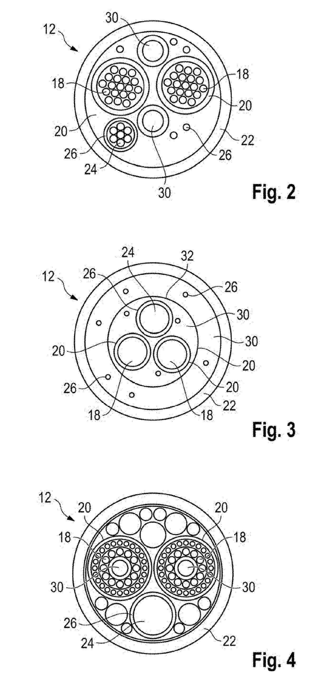
[0054]The charging cable 12 comprises two DC charging lines 18 as charging conductors with corresponding insulations 20 which are arranged in a charging cable sheath 22. The DC charging lines 18 are embodied here as DC charging lines 18 for charging with DC current and are manufactured from copper. The installations 20 of the DC charging lines 18 are fabricated from polyurethane. The charging cable sheath 22 is manufactured from polypropylene here.

[0055]Furthermore, arranged in the charging cable sheath 22 is a ground conductor 24 which is surrounded by a corresponding ground insulation 26.

[0056]Moreover, a multiplicity of signal conductors 28 with which the vehicle can communicate with the fast charging station 10 are arranged in the charging cable sheath 22.

[0057]Moreover, two fluid lines 30, in which a fluid can circulate, are formed in the charging cable sheath 22. The two fluid lines 30 are connected to the fast charging station 10 at an end thereof facing said fast charging s...

third embodiment

[0060]The charging cable 12 comprises two DC charging lines 18 with corresponding insulations 20 which are arranged in a charging cable sheath 22. The DC charging lines 18 are arranged there together with a grounding conductor 24 which is surrounded by corresponding ground insulation 26.

[0061]The charging cable 12 comprises, distributed over the cross-section of the charging cable sheath 22, a multiplicity of signal conductors 28 with which the vehicle can communicate with the fast charging station 10.

[0062]Moreover, two fluid lines 30, in which a fluid can circulate, are formed in the charging cable sheath 22. The two fluid lines 30 are arranged concentrically within the charging cable sheath 22 and separated from one another by a separating wall 32. Both the two DC charging lines 18 and the grounding conductor 24 are positioned here in a central region of the charging cable 12, within the same fluid line 30.

[0063]Also according to the third embodiment, the two fluid lines 30 are ...

fourth embodiment

[0065]The charging cable 12 comprises two DC charging lines 18 with corresponding insulations 20 which are arranged in a charging cable sheath 22. The DC charging lines 18 are arranged there together with a grounding conductor 24 which is surrounded by corresponding ground insulation 26.

[0066]The charging cable 12 illustrated in FIG. 4 also comprises a multiplicity of signal conductors 28 with which the vehicle can communicate with the fast charging station 10. However, these signal conductors 28 are not illustrated in FIG. 4.

[0067]Moreover, two fluid lines 30, in which a fluid can circulate, are formed in the charging cable sheath 22. The two fluid lines 30 are each formed concentrically within the two DC charging lines 18. Also according to the fourth embodiment, the two fluid lines 30 are connected to the fast charging station 10 at an end facing said fast charging station 10, and the two fluid lines 30 are connected to one another at an end of the charging cable 12 facing the c...


PUM


Abstract

A method for controlling the temperature of a changing cable of a fast charging station for fast charging a battery of a vehicle with en electric drive. The method includes the steps of heating the charging cable in order to form an electrical connection of the charging cable to the vehicle, sensing connection of the charging cable to the vehicle, and ending the heating of the charging cable for fast charging the battery of the vehicle. A fast charging station has a charging cable for fast charging a battery of a vehicle with an electric drive. The fast charging station is designed to carry out the above method for controlling the temperature of a charging cable

Description

CROSS-REFERENCE TO RELATED APPLICATION[0001]This application claims priority to German Patent Application No. DE 10 2018 100 731.0, filed Jan. 15, 2018, which is incorporated by reference herein in its entirety.FIELD OF THE INVENTION[0002]The present invention relates to a method for controlling the temperature of a charging cable of a fast charging station for fast charging a battery of a vehicle with an electric drive.[0003]Furthermore, the invention relates to a fast charging station having a charging cable for fast charging a battery of a vehicle with an electric drive.BACKGROUND OF THE INVENTION[0004]Vehicles with an electric drive usually comprise a drive battery which makes available electrical energy for driving the vehicle. The vehicle can be an exclusively electrically operated vehicle or what is referred to as a hybrid vehicle which, in addition to the electric drive, additionally has a further, conventional drive, typically an internal combustion engine. The drive batter...

Claims


Application Information

Patent Timeline
IPC IPC(8): B60L5/02B60R16/033H05B3/12H01B7/42
CPCB60L5/02B60R16/033H05B3/12H01B7/42B60L1/02B60L1/04B60L53/18Y02T90/16Y02T10/70Y02T90/14Y02T10/7072Y02T90/12
Inventor REBER, VOLKERGOTZ, STEFANRONFANZ, JARI
Owner DR ING H C F PORSCHE AG
Why Eureka
Try Eureka