
Multi-stage, liquid hydrogen-based aerospace system

a liquid hydrogen-based, multi-stage technology, applied in the field of aerospace technology, can solve the problems of space beyond the reach of all but the most well-funded companies and nations, rare and expensive high-speed travel within the atmosphere, and relatively high cost of iterating to explore the design space of high-speed aerospace vehicles. to achieve the effect of prolonging the tim

Inactive Publication Date: 2019-08-08
GLOBAL REACH AEROSPACE LLC
View PDF0 Cites 0 Cited by
  • Summary
  • Abstract
  • Description
  • Claims
  • Application Information

AI Technical Summary

Benefits of technology

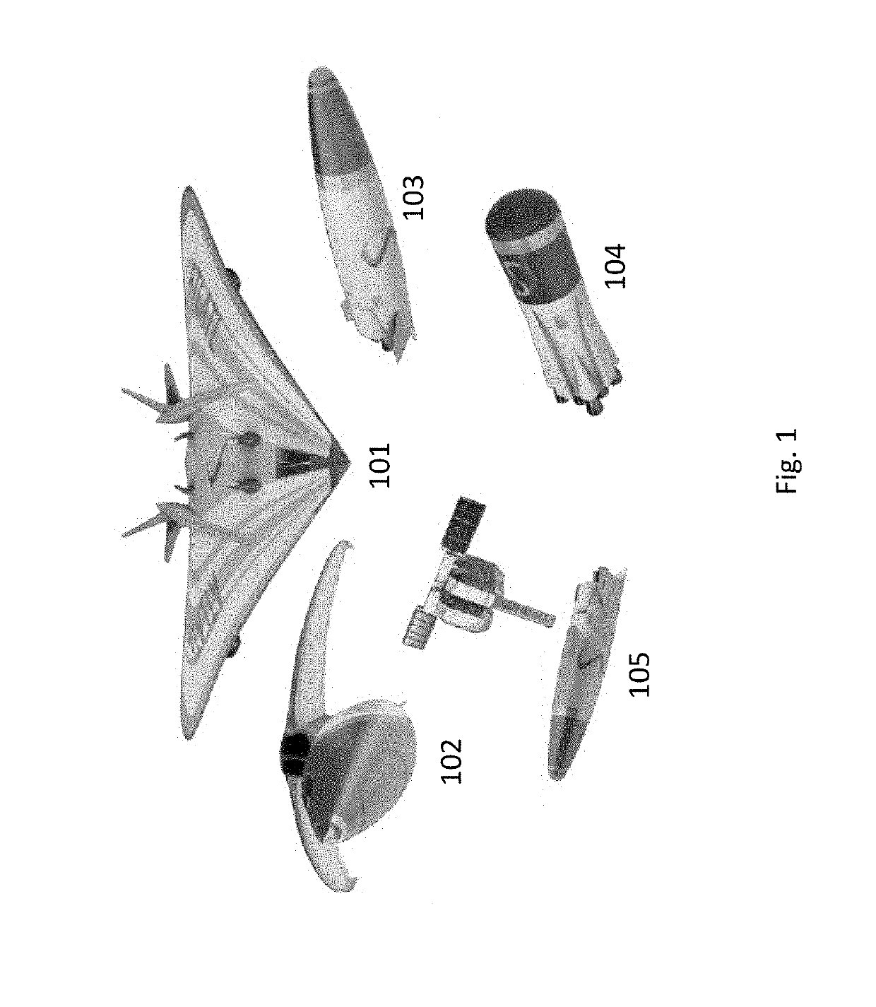
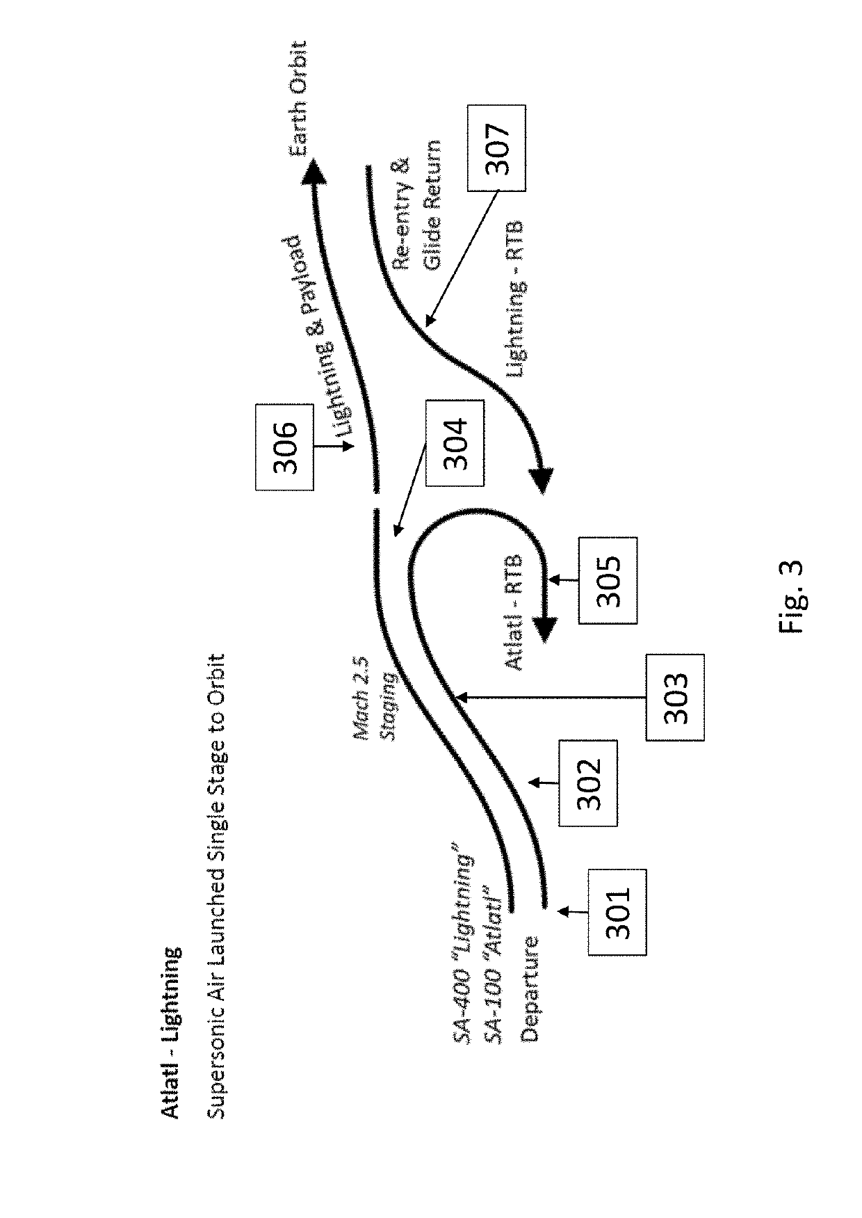
The aerospace system described in this patent is a two-stage or three-stage space access system. The first stage lifts and accelerates a rocket powered space flight vehicle to a high speed, while the second stage rocket booster provides additional thrust. For longer missions, an on-orbit fuel depot can be added to extend the time between when the space flight vehicle needs to return to Earth. The technical effect of this system is to enable safe and reliable access to space, with the ability to carry heavier payloads and extend mission duration.

Problems solved by technology

High-speed travel within the atmosphere is rare and expensive, and space is beyond the reach of all but the most well-funded companies and nations.
This is due to both the challenging physics of these endeavors and, of particular relevance, the relatively high-cost of iterating to explore the design space for high-speed aerospace vehicles.
However, testing integrated combinations of systems in real world conditions can cost hundreds of millions of dollars, or more.
Many designers have failed to analyze the problem of air and space travel holistically and, as a result, traditional systems are often optimized with components which perform well in one realm (e.g., at subsonic speeds, low in the atmosphere) but are of little use in other realms (e.g., at supersonic or hypersonic speeds, high in the atmosphere).

Method used


Image

  • Multi-stage, liquid hydrogen-based aerospace system
  • Multi-stage, liquid hydrogen-based aerospace system
  • Multi-stage, liquid hydrogen-based aerospace system

Examples


Embodiment Construction

[0014]To mitigate the problems described herein, the inventors had to both invent solutions and, in some cases just as importantly, recognize problems overlooked (or not yet foreseen) by others in the fields of aerospace and propulsion engineering. Indeed, the inventors wish to emphasize the difficulty of recognizing those problems that are nascent and will become much more apparent in the future should trends in industry continue as the inventors expect. Further, because multiple problems are addressed, it should be understood that some embodiments are problem-specific, and not all embodiments address every problem with traditional systems described herein or provide every benefit described herein. That said, improvements that solve various permutations of these problems are described below.

[0015]Some embodiments exploit a heretofore unexplored envelope in the above-described design space that is expected to afford relatively low-cost high-speed air travel within the atmosphere, as...


PUM


Abstract

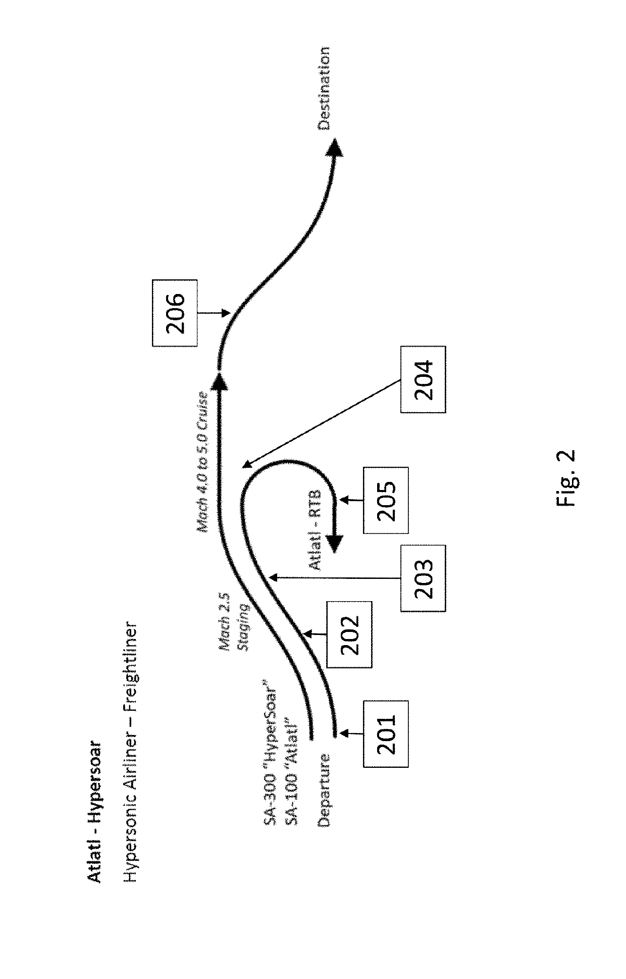
Provided are methods and systems for a modular multi-stage aerospace system having a first-stage vehicle that lifts and accelerates and is capable of achieving velocities of Mach 2.5, the first-stage vehicle powered by at least one turbine engine, and capable of autonomous and remote control; and a second-stage atmospheric flight vehicle capable of velocities of Mach 5.0, the second-stage atmospheric flight vehicle powered by at least one hydrogen-fueled turboramjet engine, and capable of carrying an internal payload; wherein the first-stage vehicle is adapted to support the second-stage atmospheric flight vehicle, as the first-stage vehicle reaches velocities sufficient to launch the second-stage atmospheric flight vehicle, and the second-stage atmospheric flight vehicle is capable of travel 12,000 miles.

Description

CROSS REFERENCE TO RELATED APPLICATIONS[0001]This application claims priority to U.S. Provisional Application No. 62 / 626,977, filed Feb. 6, 2018, entitled MULTI-STAGE, LIQUID HYDROGEN-BASED AEROSPACE SYSTEM, U.S. Provisional Application No. 62 / 634,892, filed Feb. 23, 2018, entitled LARGE TEST AREA COMPRESSED AIR WIND TUNNEL, and U.S. Provisional Application No. 62 / 634,297 entitled SUPERSONIC HYDROGEN FUEL TURBOJET ENGINE, filed Feb. 23, 2018.BACKGROUND1. Field[0002]The present disclosure relates generally to aerospace technology and, more specifically, to multi-stage, liquid hydrogen-based aerospace systems.2. Description of the Related Art[0003]High-speed travel within the atmosphere is rare and expensive, and space is beyond the reach of all but the most well-funded companies and nations. This is due to both the challenging physics of these endeavors and, of particular relevance, the relatively high-cost of iterating to explore the design space for high-speed aerospace vehicles. M...

Claims


Application Information

Patent Timeline
IPC IPC(8): B64G1/00B64G1/40F02K7/16
CPCB64G1/005B64G1/401F02K7/16B64G1/62B64G1/006B64G1/1081B64D5/00
Inventor CARTER, PRESTON HENRY
Owner GLOBAL REACH AEROSPACE LLC
Learn More