Rolling piston ring, piston and cylinder

a technology of rolling piston and cylinder, applied in the mechanical field, can solve the problems of poor lubrication condition, large pressure, and inability to come up with a true rolling piston ring, and achieve the effects of greatly reducing friction, greatly improving efficiency, and greatly reducing friction

Active Publication Date: 2019-08-08
LI ZHONGFU
View PDF0 Cites 0 Cited by
  • Summary
  • Abstract
  • Description
  • Claims
  • Application Information

AI Technical Summary

Benefits of technology

[0019]1. The sliding friction of the original piston ring is changed into rolling friction, wherein the friction is greatly reduced, and the efficiency is greatly improved.
[0020]2. If heat engine and other machines are damaged during work, wear and tear must the most important factor, and the piston and the cylinder are first worn out. After the fric...

Problems solved by technology

It is known that the rolling friction is much smaller than the sliding friction, but humans have not yet come up with a true rolling piston ring.
The sliding friction is large between the piston ring and the cylinder wall, wherein the lubrication condition is poor and the pressure is large.
The great pressure must have a lot of friction, so these two patents changed the original weak sliding friction to rolling friction, but the place with large sliding friction is not changed to rolling friction, which cannot greatly reduce the friction.
These two applications do not provide a solution to how to ensure that the rolling element for sealing does not get stuck during thermal ex...

Method used


Image

  • Rolling piston ring, piston and cylinder
  • Rolling piston ring, piston and cylinder
  • Rolling piston ring, piston and cylinder

Examples


embodiment 1

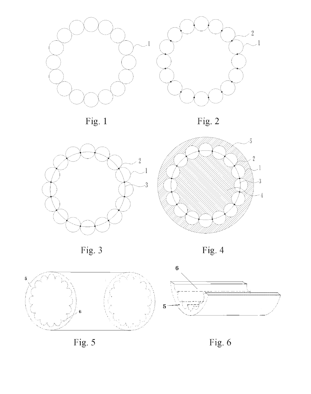
[0072]FIGS. 4-7 show a piston 4 with a circular external contour, a piston ring which is a ball ring 1, a cylinder 5, a recess-shaped slide 6 formed by a plurality of arc in a radical direction and a plurality of partially cylindrical face in an axial direction, and a spherical recess 7 on the piston 4. The ball ring 1, the slide 6 and the recess 7 are fitted together. The ball ring 1 can in-situ roll in the recess 7 of the piston 4, as well as reciprocate on the slide 6 on an internal wall of the cylinder 5, so as to seal the circular piston 4 and the circular cylinder 5.

[0073]When an outer diameter of the circular cylinder 5 is constant and a thickness of the cylinder 5 is slightly changed, original balls can be separated on an outer side by small ball, for moving contact points outwards. Furthermore, moving a contact point face outwards can increase a cross section of the piston 4, and vice versa. The cross section of the piston 4 is greatly changed by changing the rolling piston...

embodiment 2

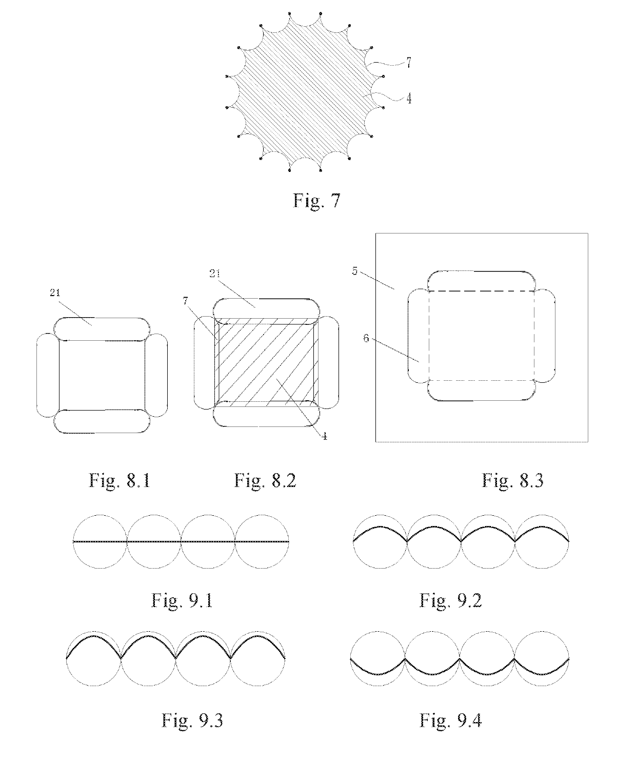
[0074]FIGS. 8.1-8.3 show a piston 4 with a square external contour, a piston ring which is a column ring 21, a square cylinder 5, a flat-bottom slide 6 on an internal wall of the cylinder with arcs at two ends, and a column recess 7 with two convex ends on the piston 4. The column ring 21, the slide 6 and the column recess 7 are fitted together. The column ring 21 can in-situ roll in the recess 7, as well as reciprocate on the slide 6 on the internal wall of the cylinder 5, so as to seal the piston 4 and the cylinder 5.

[0075]Referring to FIGS. 16.1-16.3, The cross section of the piston is square, and the column on each side of the column ring may be integrated, wherein a length and a thickness of each column may be equal or unequal. If the length is not equal, there may be three kinds of columns with long, medium and short lengths (a, b, c respectively). The maximum length difference between the long and the middle columns or the middle and the short columns equals to a diameter of ...

embodiment 3

[0076]The cross-sectional shape of the piston, the shape of the rolling ring, the overall shape of the cylinder internal contour and the shape of the cylinder head are consistent or nearly identical to the cross-sectional shape of the combustion chamber, and the rolling ring, the recess of the piston, the slide on the internal wall of the cylinder are fitted, so as to seal the piston and the cylinder.

[0077]Since the conventional piston ring of the internal combustion engine is circular, the internal contour of the cylinder and the external contour of the piston are both circular, which is not matched with the combustion chamber of a non-circular cross section. A part of the piston is not subject to the gas thrust, resulting in large mass and inertia of the cylinder and the piston. Nowadays, the rolling ring of the present invention may be non-circular, which can change the shape of the cross section of the piston so as to correspond to the cross-sectional shape of the combustion cha...


PUM


Abstract

A rolling piston installed between a piston and a cylinder includes: a plurality of balls, wherein the balls are connected end to end to form the rolling piston ring, and a quantity of the balls is no less than three; or comprising: a plurality of columns, wherein the columns are connected end to end to form the rolling piston ring, and a quantity of the balls is no less than three; or comprising: balls and columns, wherein the balls and the columns are connected end to end to form the rolling piston ring, and a total quantity of the balls and the columns is no less than three; wherein both the balls and the columns are extendable, and/or a recess on the piston for installing the rolling piston ring is extendable and a slide on the cylinder for installing the rolling piston ring is extendable.

Description

CROSS REFERENCE OF RELATED APPLICATION[0001]The present invention claims priority under 35 U.S.C. 19(a-d) to CN 201810577905.3, filed Jun. 7, 2018.BACKGROUND OF THE PRESENT INVENTIONField of Invention[0002]The present invention relates to a mechanical field which is especially suitable for internal combustion engines, slurry pumps, air compressors, reciprocating impact devices, hydraulic cylinders or cylinders, and more particularly to a rolling piston ring, a corresponding piston and a cylinder.Description of Related Arts[0003]The friction between the piston ring and the cylinder conventionally installed on the piston is sliding friction. It is known that the rolling friction is much smaller than the sliding friction, but humans have not yet come up with a true rolling piston ring.[0004]Chinese patent applications CN 103291450A and CN 103291602A disclose a piston rolling friction for the purpose of changing the sliding friction between the piston and the cylinder into rolling frict...

Claims


Application Information

Patent Timeline
IPC IPC(8): F16J1/02
CPCF16J1/02F16J1/08F16J9/22F16J10/04F16J9/12
Inventor LI, ZHONGFU
Owner LI ZHONGFU
Why Eureka
Try Eureka