System and Method for Separating a Tubular Component

a technology of separating system and tubular component, which is applied in the direction of gas flame welding apparatus, hollow objects, and auxillary devices for welding, etc., can solve the problems of no system, large portion of erection cost associated with tube production, and increasing construction logistics. problems, to achieve the effect of reducing effort, high degree of precision and quality

Active Publication Date: 2019-08-22
FRAUNHOFER GESELLSCHAFT ZUR FOERDERUNG DER ANGEWANDTEN FORSCHUNG EV
View PDF1 Cites 3 Cited by
  • Summary
  • Abstract
  • Description
  • Claims
  • Application Information

AI Technical Summary

Benefits of technology

[0013]The object underlying the invention is to improve a system for separating a tubular component that is suitable for constructing a supporting structure, in particular in the form of offshore or bridge constructions in such manner that pipe sockets can be cut to size with a high degree of precision and very exactly, and this may be erected with a separating arrangement that can be moved without excessive transport and installation effort for use at any depl

Problems solved by technology

In this context, a large portion of the erection costs are associated with the production of the tube joints, which are constructed as welded joints representing tube-tube connections.
Moreover, in view of the unceasing development of new erection sites which are usually very remote from each other, questions of concern such as construction logistics are becoming more and more pressing.
To date, there are no systems in existence that combine both trimming a pipe socket and welding the pipe joints in one comprehensive solution.
The known pipe cutting systems based on the abovementioned system concept are of necessity limited to a fixed position system installation because of the very large assembly space they occupy and the substantial total weight of the equipment, and their deployment to another production site is associated with very considerable expense.
A further disadvantage relates to the handling of the part separated from the pipe segment, referred to as the “bad part”, which only drops off the pipe segment or is transported away in an inconsistently controlled way.
This can cause locally limited impairment of the quality of the cut and damage to system components or even to the pipe segment that is to be cut.
The intense handling effort that must be applied in order to shift the good part which is cut to size and mount

Method used


Image

  • System and Method for Separating a Tubular Component
  • System and Method for Separating a Tubular Component
  • System and Method for Separating a Tubular Component

Examples


Embodiment Construction

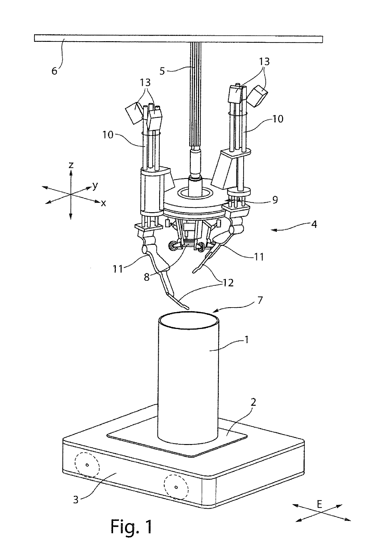
[0039]FIG. 1 is a perspective showing a diagrammatic view of the system according to the invention for separating a tubular component 1, which in

[0040]FIG. 1 is a straight steel cylinder supported on a horizontally oriented receiving platform 2 of a mobile transport module 3, which travels freely along a production plane E. The mobile transport module 3 illustrated in FIG. 1 is preferably a low-loader transport vehicle. Alternatively, it is also possible to implement the mobile transport module 3 in the form of other load-bearing vehicles with carrier function or devices that are operable in the production plane.

[0041]The system according to the invention also provides a separating arrangement 4 which is separate for the mobile transport module 3 and also separate from the tubular component 1. The separating arrangement is supported on a supporting structure 6 such that it can be at least raised and lowered vertically by means of a suspension assembly 5, preferably via cable winches...


PUM

PropertyMeasurementUnit
Forceaaaaaaaaaa

Abstract

A system and a method for separating a tubular component is disclosed, which for constructing a supporting structure, having a longitudinal pipe with pipe ends which are open on both sides. The system has a mobile transport module comprising a receiving platform having a pipe clamping device for clamping variable pipe diameters which receives and mounts the tubular component so that a first pipe end of the component, having a vertical longitudinal axis which detachably and securely engages the pipe clamping device. The invention further relates to a separating arrangement mounted on a supporting structure that it is deflectable at least vertically, to provide secure joining to the pipe end of a tubular component that faces away from the first pipe end. The tubular component is seated on the transport module and vertically securely engages the pipe clamping device.

Description

CROSS REFERENCE TO RELATED APPLICATIONS[0001]Reference is made to PCT / EP2017 / 071742 filed Aug. 30, 2017, and German Application No. 10 2016 216 388.4 filed Aug. 31, 2016, which are incorporated herein by reference in their entirety.BACKGROUND OF THE INVENTIONField of the Invention[0002]The invention relates to a system and a method for separating a tubular component which is suitable for constructing a supporting structure, in particular in the form of offshore or bridge constructions and has a longitudinal pipe with pipe ends that are open on both sides.Description of the Prior Art[0003]Amid the growing trend towards abandoning conventional energy generating systems, efforts to develop sources of renewable energies are advancing unabated. In order to achieve the stated energy transition objectives, offshore wind turbines are expected to contribute substantially to power generation requirements. As a consequence, the output of wind turbines currently in development is increasing ste...

Claims


Application Information

Patent Timeline
IPC IPC(8): B23K7/00B23K7/10B23K37/02B25J9/00
CPCB23K7/007B23K7/10B23K37/02B23K37/0217B23K37/0276B25J9/0018B23K2101/06B23K2103/04B23K2101/10
Inventor WANNER, MARTIN CHRISTOPHHERHOLZ, HAGENKLOETZER, CHRISTIAN
Owner FRAUNHOFER GESELLSCHAFT ZUR FOERDERUNG DER ANGEWANDTEN FORSCHUNG EV
Why Eureka
Try Eureka