Central processing unit cache friendly multithreaded allocation

a multi-threaded allocation and central processing unit technology, applied in the field of central processing unit cache friendly multi-threaded allocation, can solve the problems of increasing filesystem latency and achieve the effect of improving the performance of a hybrid storage device and affecting the overall performan

Active Publication Date: 2019-08-22
MICROSOFT TECH LICENSING LLC
View PDF1 Cites 3 Cited by
  • Summary
  • Abstract
  • Description
  • Claims
  • Application Information

AI Technical Summary

Benefits of technology

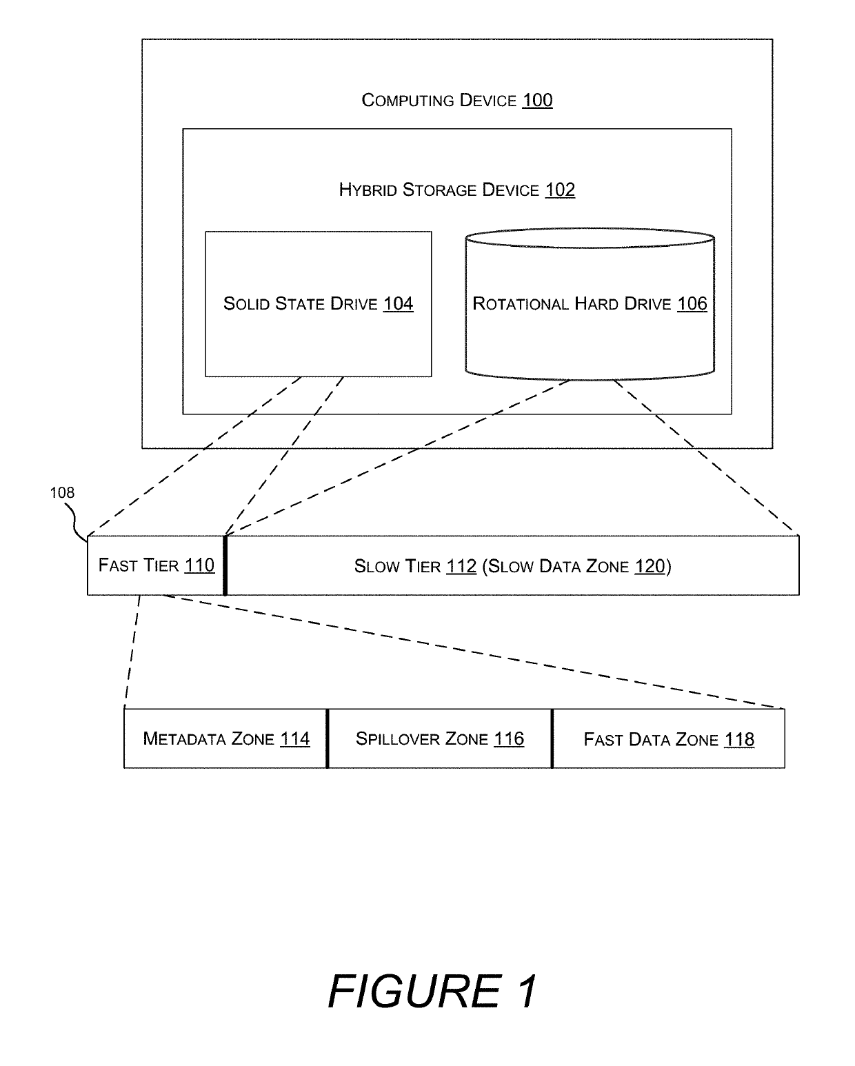
[0007]One goal of the disclosed embodiments is to improve the performance of a hybrid storage device. Hybrid storage devices combine multiple physical storage devices formatted as a single logical filesystem volume. Each of the physical storage devices, or tiers, may have different performance characteristics, and so selectively storing different types of data on differently performant tiers can have a significant impact on overall performance.
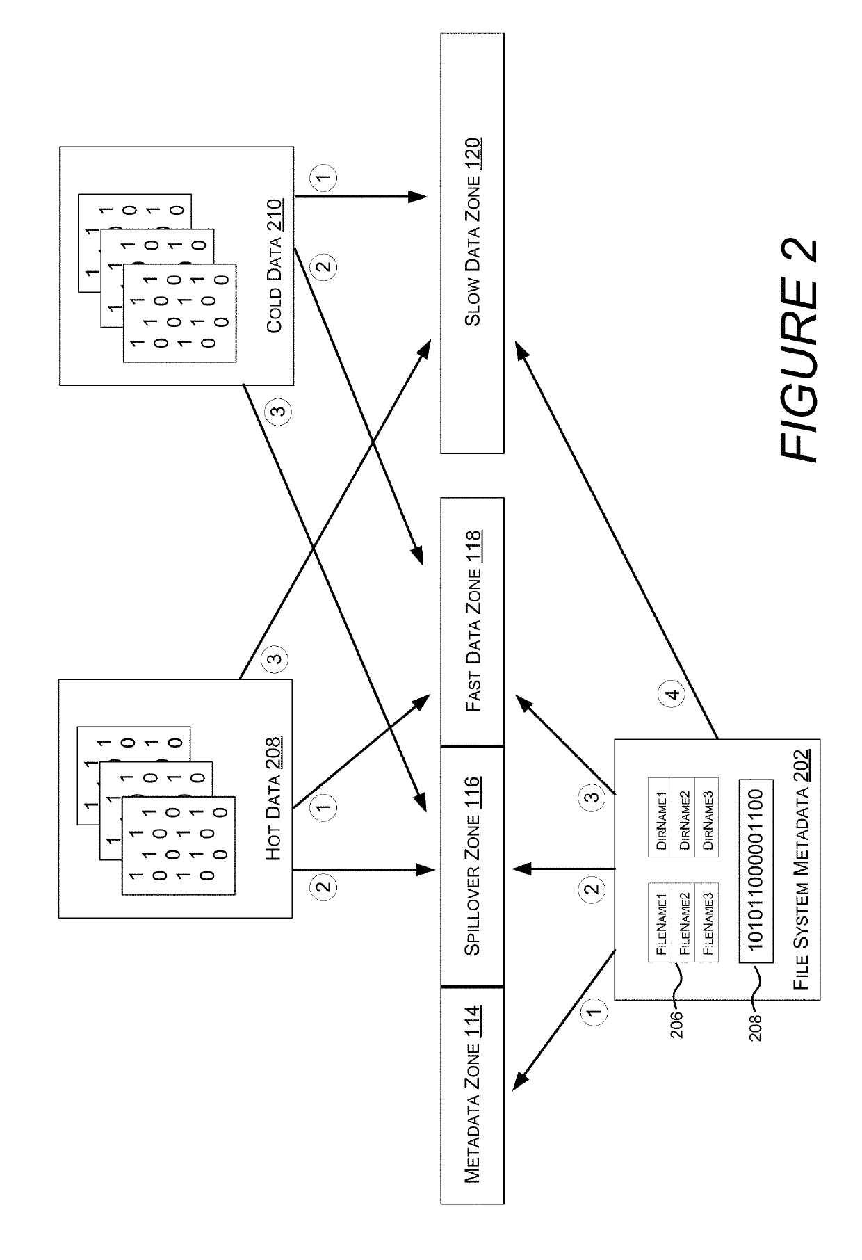
[0008]A filesystem controls how data is stored and retrieved from a storage device. For example, a filesystem may enable data to be stored in files, which are located in a directory structure. The filesystem tracks files and directories with metadata, which is also stored on the underlying storage device. Other types of metadata ensure integrity of the filesystem in the event of an unexpected error, provide for recovery of lost data, improve performance by enabling optimizations, and the like. Metadata has a central role in filesystem operations, and metadata operations are often performed while holding locks, increasing filesystem latency. As such, overall filesystem performance is sensitive to the performance metadata operations. Therefore, in one embodiment, metadata is preferentially stored on higher performant tiers, e.g. an SSD in a hybrid storage device containing an SSD and a rotational hard drive (HDD).

Problems solved by technology

Metadata has a central role in filesystem operations, and metadata operations are often performed while holding locks, increasing filesystem latency.

Method used


Image

  • Central processing unit cache friendly multithreaded allocation
  • Central processing unit cache friendly multithreaded allocation
  • Central processing unit cache friendly multithreaded allocation

Examples


example clauses

[0122]Example Clause A, a method for storage allocation on a computing device comprising a multi-core central processing unit (CPU), each CPU core having a non-shared cache, the method comprising: receiving, at a filesystem allocator, a plurality of storage allocation requests, each executing on a different core of the multi-core CPU, wherein the storage allocation requests are for a file system volume that is divided into bands composed of a plurality of storage clusters, and wherein, for each band, storage clusters are marked as allocated or unallocated by a corresponding cluster allocation bitmap; dividing a cluster allocation bitmap into a plurality of chunks, wherein each chunk is the size of a cache line of the non-shared cache, wherein each chunk is aligned in system memory with the non-shared cache lines of the non-shared cache, and wherein a chunk status bitmap indicates which of the plurality of chunks has at least one unallocated cluster; determining a maximum number of s...


PUM


Abstract

A cluster allocation bitmap determines which clusters in a band of storage remain unallocated. However, concurrent access to a cluster allocation bitmap can cause CPU stalls as copies of the cluster allocation bitmap in a CPU's level 1 (L1) cache are invalidated by another CPU allocating from the same bitmap. In one embodiment, cluster allocation bitmaps are divided into L1 cache line sized and aligned chunks. Each core of a multicore CPU is directed at random to allocate space out of a chunk. Because the chunks are L1 cache line aligned, the odds of the same portion of the cluster allocation bitmap being loaded into multiple L1 caches by multiple CPU cores is reduced, reducing the odds of an L1 cache invalidation. The number of CPU cores performing allocations on a given cluster allocation bitmap is limited based on the number of chunks with unallocated space that remain.

Description

BACKGROUND[0001]Computer storage needs continue to increase, both in terms of capacity and performance. For many years hard disk drives based on rotating magnetic media dominated the storage market, providing ever increasing density and throughput combined with low latency. However, for certain applications even better performance was desired, and so solid-state drives (SSDs) were introduced that out-performed traditional hard drives, yet cost significantly more per byte of storage.[0002]Some computing applications are more sensitive to differences in storage performance than others. For example, core operating system functions, low latency applications such as video games, storage focused applications such as databases, and the like benefit more from the increased performance of an SSD than web browsing, media consumption, and other less storage intensive tasks. Similarly, computing tasks that perform a significant number of random access storage operations, as opposed to streaming...

Claims


Application Information

Patent Timeline
Patent Type & Authority Applications(United States)
IPC IPC(8): G06F12/0873G06F12/0817G06F12/0808G06F9/38
CPCG06F12/0808G06F12/0873G06F9/3891G06F2212/608G06F12/0828G06F12/0238G06F2212/1016G06F2212/45G06F2212/7207
Inventor CAREY, OMARDAS, RAJSEKHAR
Owner MICROSOFT TECH LICENSING LLC
Why Eureka
Try Eureka