
Systems and methods for power production using a carbon dioxide working fluid
a technology of working fluid and carbon dioxide, which is applied in the direction of machines/engines, mechanical equipment, separation processes, etc., can solve the problems of increasing costs due to the need for added equipment, requiring significant power consumption, and no longer having sufficient heat content in the exhaust stream of turbines
- Summary
- Abstract
- Description
- Claims
- Application Information
AI Technical Summary
Benefits of technology
Problems solved by technology
Method used
Image

Examples
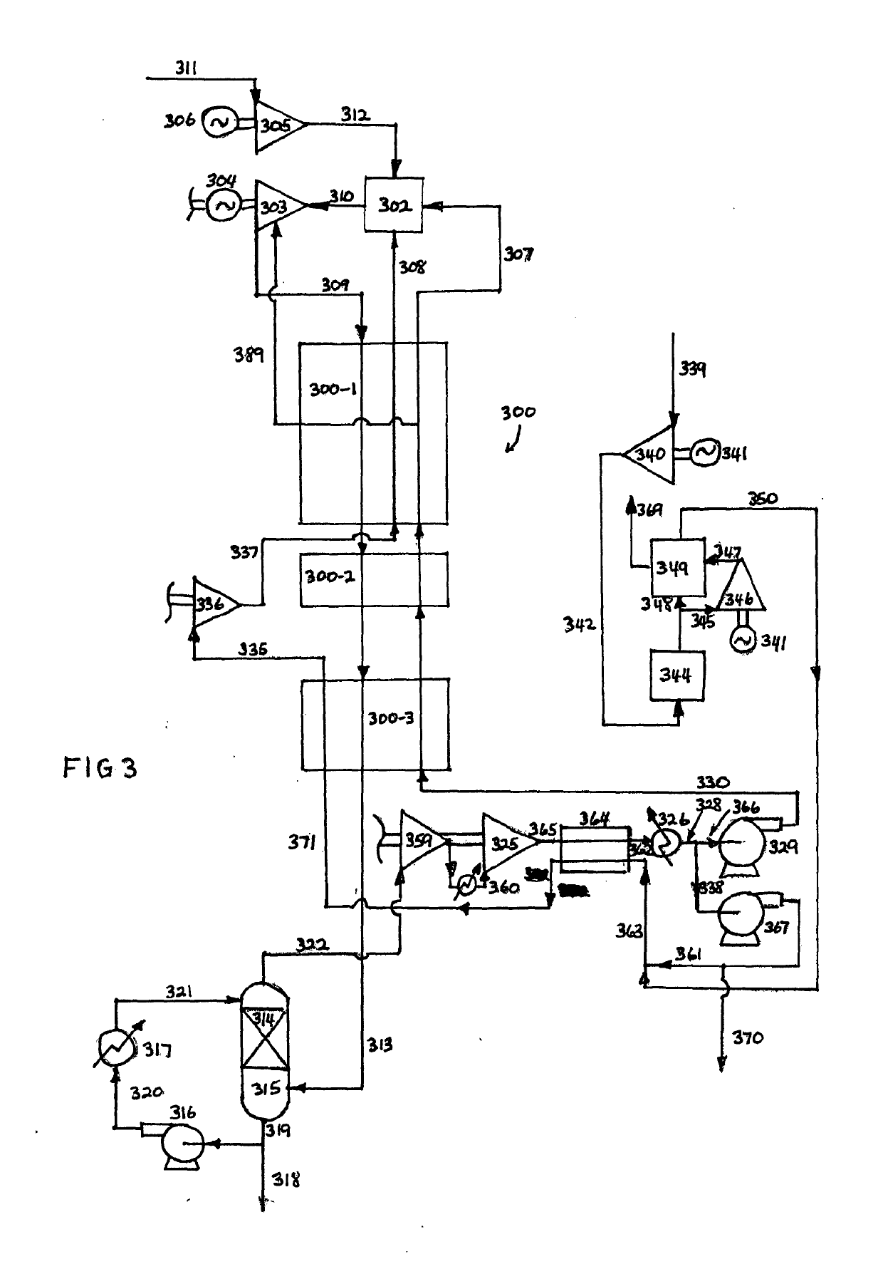
example 1 (embodiment according to fig.3)
Example 1 (Embodiment According to FIG. 3)
[0080]
Turbine inlet condition1212° C. and 300 barTurbine cooling and seal gas flow10% of turbine outlet flowTurbine outlet condition720° C. and 20 barOxygen flow rate4120.9 metric tons per dayTurbine power492.7MwParasitic power for O2 plus143.79MwCH4 and CO2 compressionNet power output348.97MwMethane fuel power potential595MwRecycle CO2 at 3043,098,320Kg / Hrbar entering recuperator HxNet efficiency58.65%(LHV)
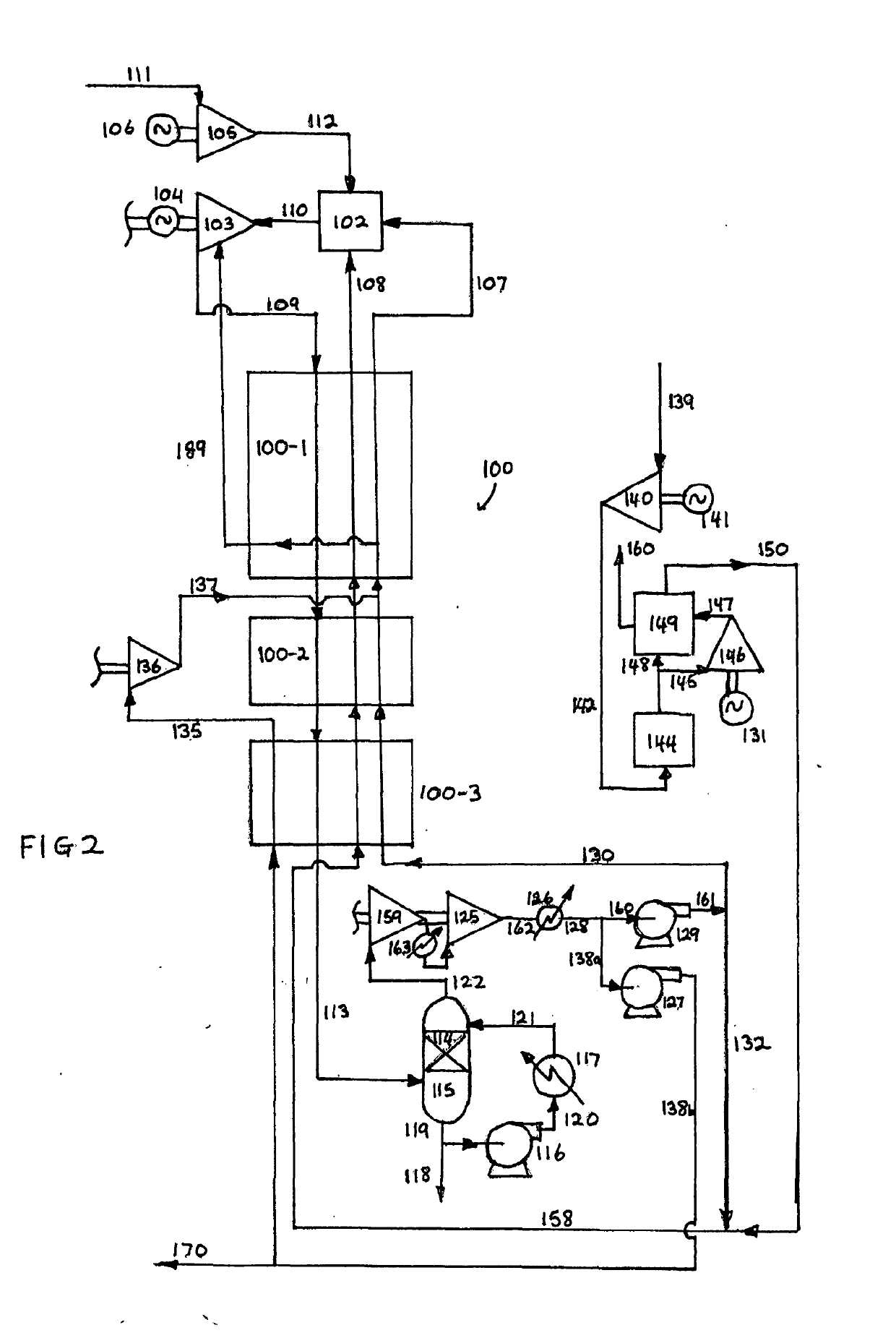
example 2 (embodiment according to fig.2)
Example 2 (Embodiment According to FIG. 2)
[0081]
Turbine inlet condition1520° C. and 300 barTurbine cooling and seal gas flow10% of turbine outlet flowTurbine outlet condition707° C. and 4 barTurbine power904.4MwParasitic power for O2 plus255.1MwCH4 and CO2 compressionNet power output649.3MwMethane fuel power potential927.21MwRecycle CO2 at 3043,131,657Kg / Hrbar entering recuperator HxNet efficiency70.0%(LHV)
PUM
 Abstract
Description
Claims
Application Information