
Thermal interposer for a cryogenic cooling system

Active Publication Date: 2019-09-12
GENERAL ELECTRIC CO
View PDF0 Cites 0 Cited by
  • Summary
  • Abstract
  • Description
  • Claims
  • Application Information

AI Technical Summary

Benefits of technology

This patent describes a cooling system for hyperpolarized samples used in magnetic resonance imaging (MRI). The system includes a cryogenic chamber, a cooling plate, a sample sleeve, a thermal switch, and an interposer. The cooling plate is in contact with the cryogenic fluid and has a coated surface to prevent contamination. The sample sleeve is at least partially inserted in the cryogenic chamber and has a coated surface to prevent contamination. The thermal switch is located between the cooling plate and the sample sleele and includes a coated surface to prevent contamination. The interposer is located between at least one of the thermal switch and the cooling plate, and / or the thermal switch and the sample sleeve, and includes a gallium indium tin alloy. The system can cool a sample to a low temperature (<2 K) for use in MRI. This cooling system can improve the efficiency and accuracy of MRI procedures using hyperpolarized samples.

Problems solved by technology

Sensitivity of nuclear magnetic resonance (NMR) systems, such as magnetic resonance imaging (MM) systems, are often limited due to the normally very low polarization of the nuclear spins of samples being used.
However, indium requires a high pressure to be applied at the contact surfaces from room temperature down to cryogenic temperatures to balance thermal shrinkage of indium during cooling.

Method used


Image

  • Thermal interposer for a cryogenic cooling system
  • Thermal interposer for a cryogenic cooling system
  • Thermal interposer for a cryogenic cooling system

Examples


example

[0047]The following example is presented to further illustrate non-limiting embodiments of the present specification.

[0048]Two copper plated Inconel plates were used as top and bottom plates for the experiment. Both the top plate and the bottom plate were brush painted with a eutectic gallium indium tin alloy (alternatively, Galinstan®) having about 66.71 atomic % of gallium, about 20.38 atomic % of indium, and about 12.91 atomic % of tin. Galinstan coated surfaces of the top plate and the bottom plate were contacted with each other making the Galinstan® as an interposer between the top and the bottom plates. Temperature sensors were attached to both the top plate and the bottom plate. Heat was applied to the bottom plate and temperatures of the bottom plate and the top plate were measured at various temperatures.

[0049]FIG. 4 shows a graphical comparison 400 of cool down curves of the bottom plate (i.e., hot plate) and the top plate (i.e., cold plate). It can be seen from the graph ...


PUM


Abstract

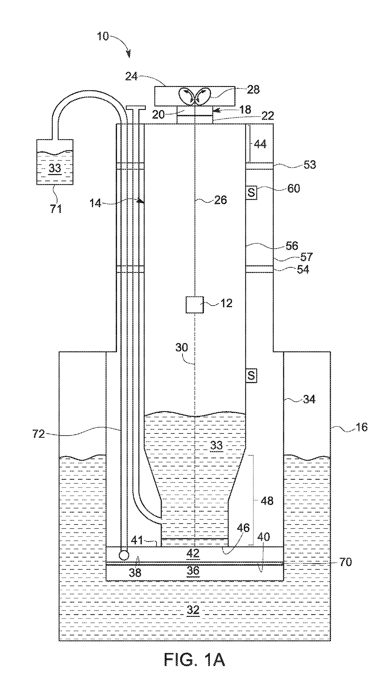
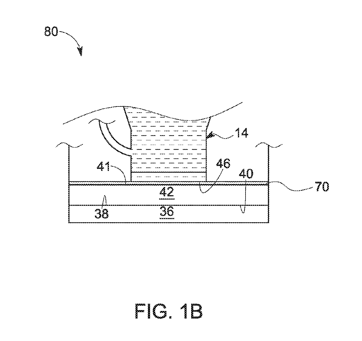
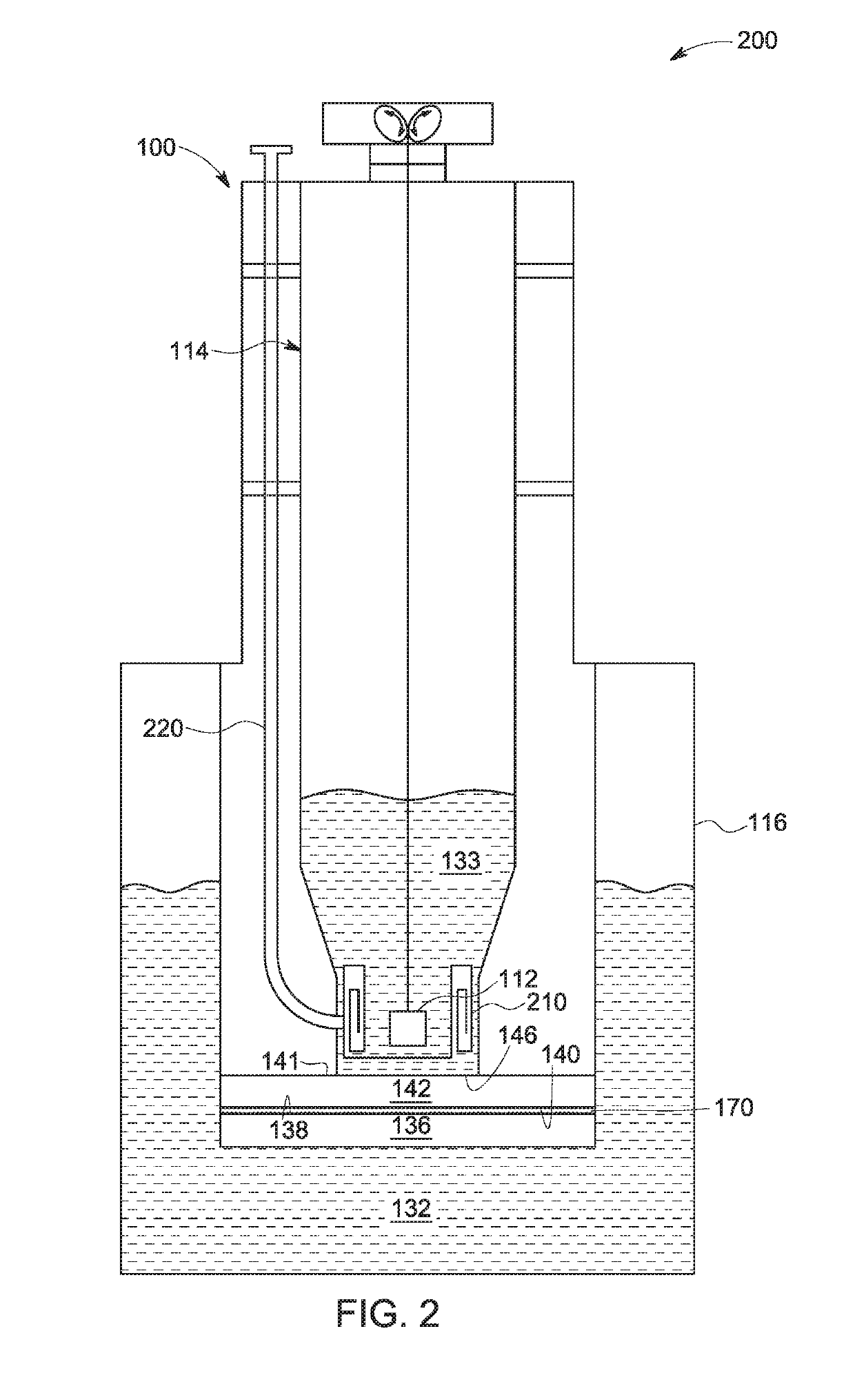
A cooling system, an apparatus for producing hyperpolarized samples, where the apparatus includes the cooling system, and a method for assembling and using the cooling system are disclosed. The cooling system includes a cryogenic chamber, a cooling plate, a sample sleeve, a thermal switch, and an interposer. Also, the cryogenic chamber includes a cryogenic fluid and the cooling plate is disposed in the cryogenic chamber, in contact with the cryogenic fluid. Further, the sample sleeve is configured to receive a sample. The sample sleeve is at least partially inserted in the cryogenic chamber. The thermal switch is disposed between the cooling plate and the sample sleeve. Moreover, the interposer is disposed between at least one of (i) the thermal switch and the cooling plate and (ii) the thermal switch and the sample sleeve. The interposer includes a gallium indium tin alloy.

Description

BACKGROUND[0001]Embodiments of the present specification relate generally to cooling systems, and more particularly to a cryogenic cooling system having a thermal interposer and method for assembling and using the cryogenic cooling system.[0002]Sensitivity of nuclear magnetic resonance (NMR) systems, such as magnetic resonance imaging (MM) systems, are often limited due to the normally very low polarization of the nuclear spins of samples being used. A number of techniques exist to improve the polarization of nuclear spins in the solid phase. Dynamic nuclear polarization (DNP) is a technique that is used to generate an excess of a nuclear spin orientation relative to other spin orientations, which may sometimes be referred to as hyperpolarization. The excess of one spin orientation over another is reflected by an increase in the signal-to-noise ratio of measurements in the NMR systems. During imaging, a polarized metabolic imaging agent sample is introduced or injected into the subj...

Claims


Application Information

Patent Timeline
IPC IPC(8): G01N24/08F25D19/00F25D29/00F28F13/00F28F21/08G01N1/42G01N35/00G01R33/28
CPCF28F2013/008G01R33/282F28F21/086F28F21/085G01N24/08G01N1/42F25D19/006F25D29/001G01N35/00F28F13/00G01R33/31
Inventor STAUTNER, ERNST WOLFGANGBUDESHEIM, ERIC GEORGE
Owner GENERAL ELECTRIC CO
Features
  • Generate Ideas
  • Intellectual Property
  • Life Sciences
  • Materials
  • Tech Scout
  • Unparalleled Data Quality
  • Higher Quality Content
  • 60% Fewer Hallucinations
Learn More