Method Of Producing A Component With Additive Manufacturing

a technology of additive manufacturing and component, applied in the direction of additive manufacturing process, foundry pattern, forging, casting, etc., can solve the problems of time-consuming and expensive conventional production methods, many metal components are difficult to design, and many metal components are difficult to forge, cast, or otherwise produce, etc., to achieve efficient production of high-quality metal components and enhance mechanical and metallurgical properties

Inactive Publication Date: 2019-09-19
WELDALOY PROD CO
View PDF0 Cites 10 Cited by
  • Summary
  • Abstract
  • Description
  • Claims
  • Application Information

AI Technical Summary

Benefits of technology

[0009]In this way, the method affords advantages for efficiently producing high quality metal components such as those used in aerospace. In some embodiments the method can be employed to solve manufacturing challenges associated with the production of thrust chambers. For example, in many embodiments, the use of the exoskeleton, the formation of the additive structure with the additive manufacturing process, and the removal of the exoskeleton to form the cooling channels in the thrust chamber eliminates problems associated with the use of machining and an overlay to form cooling channels. Further, the formation of the additive structure with the additive manufacturing process eliminates problems associated with an interface between a base of one material, e.g. copper, and overlay of another, e.g. nickel which is associated with the use of machining and an overlay to form cooling channels. In such embodiments, the method efficiently yields thrust chambers of complex design which are defect free and have enhanced mechanical and metallurgical properties.

Problems solved by technology

Metal components of complex geometry, e.g. aerospace components, having various shapes and internal passages and cavities therein may be difficult to forge, cast, mill, machine, weld, braze, or otherwise produce.
In fact, many such metal components are design limited by conventional production methods.
Further, conventional production methods can be time-consuming and expensive, and can yield metal components of varying dimensional integrity and quality.
Many such methods can preclude various design features, and often yield components of inconsistent quality with respect to dimensional integrity and surface finish.
Such conventional methods of producing thrust chambers are complex and require long lead times. Further, such conventional methods produce lower yields and metal components of inconsistent quality.
For example, the machining of the cooling channels during production of the thrust chamber with such conventional methods can be time consuming and provide cooling channels with limited dimensional tolerances.
Further, because the nickel alloy overlay used in the production of the thrust chamber with these conventional methods is cast and bonded to the copper base to complete the formation of the cooling channels, various fit and finish issues associated with overlay's dimensional tolerances are introduced and a potential failure mode is created at the bond line where the copper base and the nickel alloy overlay interface.
As such, such conventional methods of production can limit the yield and quality of the thrust chambers produced.

Method used


Image

  • Method Of Producing A Component With Additive Manufacturing
  • Method Of Producing A Component With Additive Manufacturing
  • Method Of Producing A Component With Additive Manufacturing

Examples


Embodiment Construction

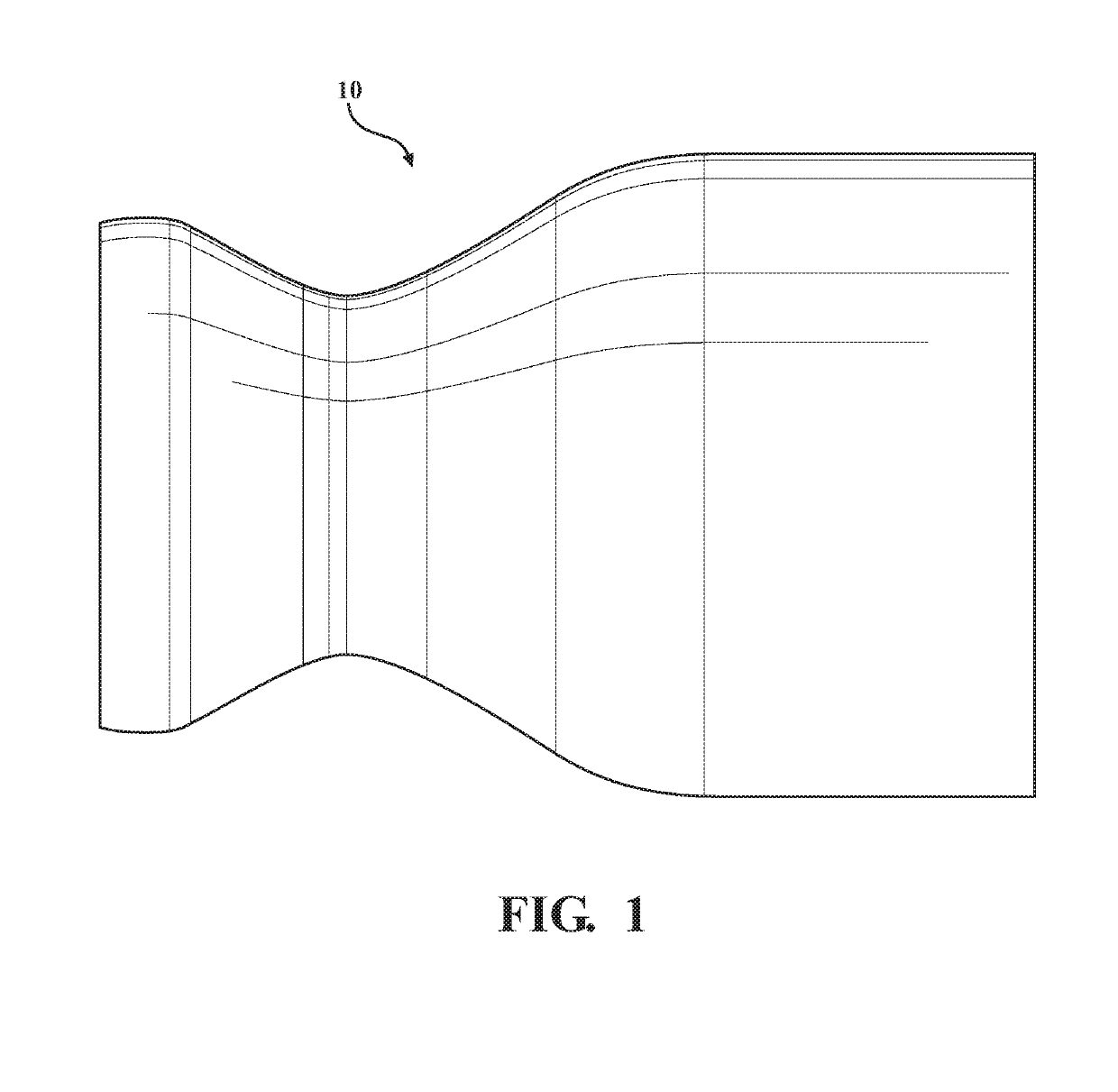
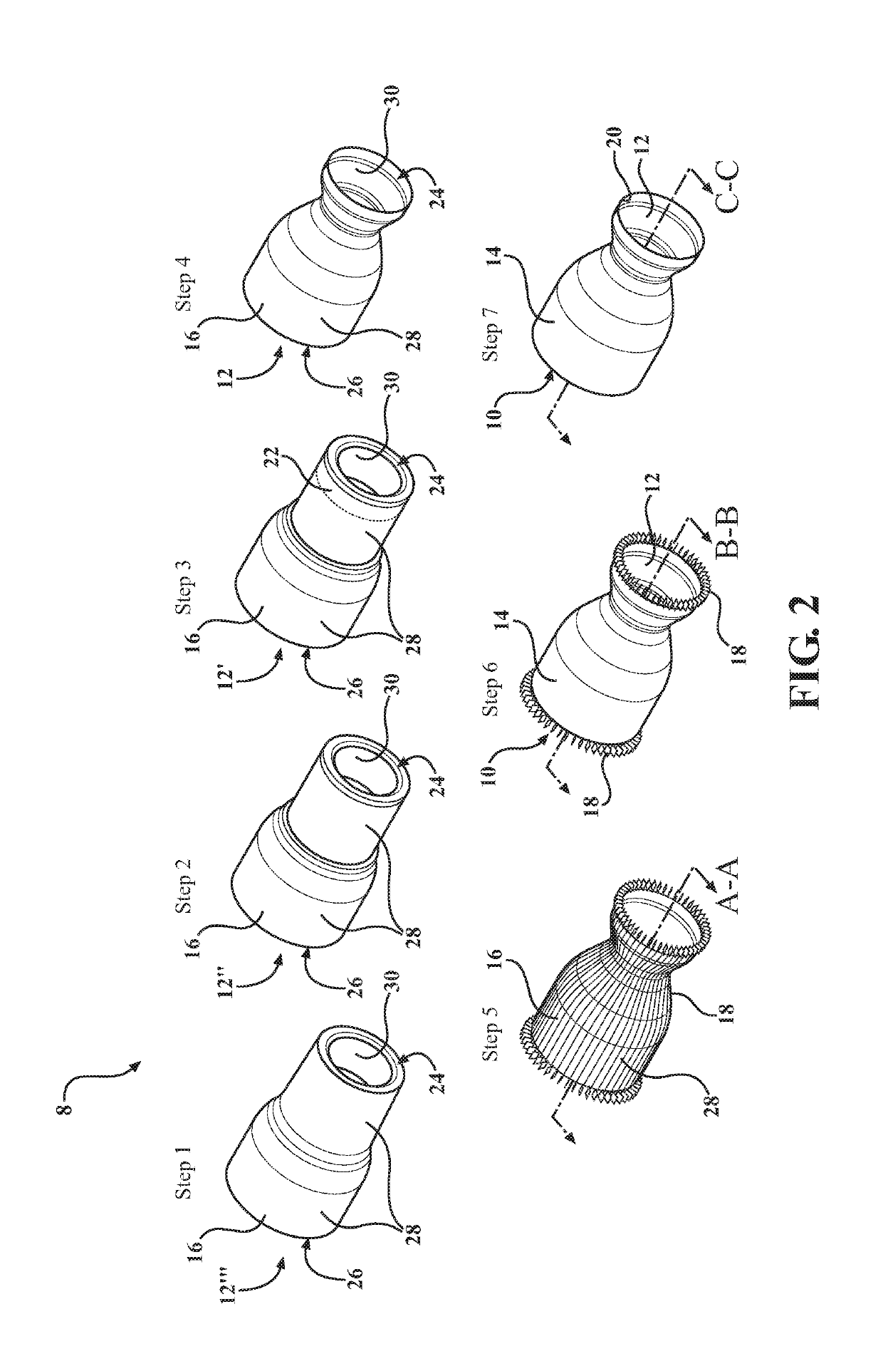
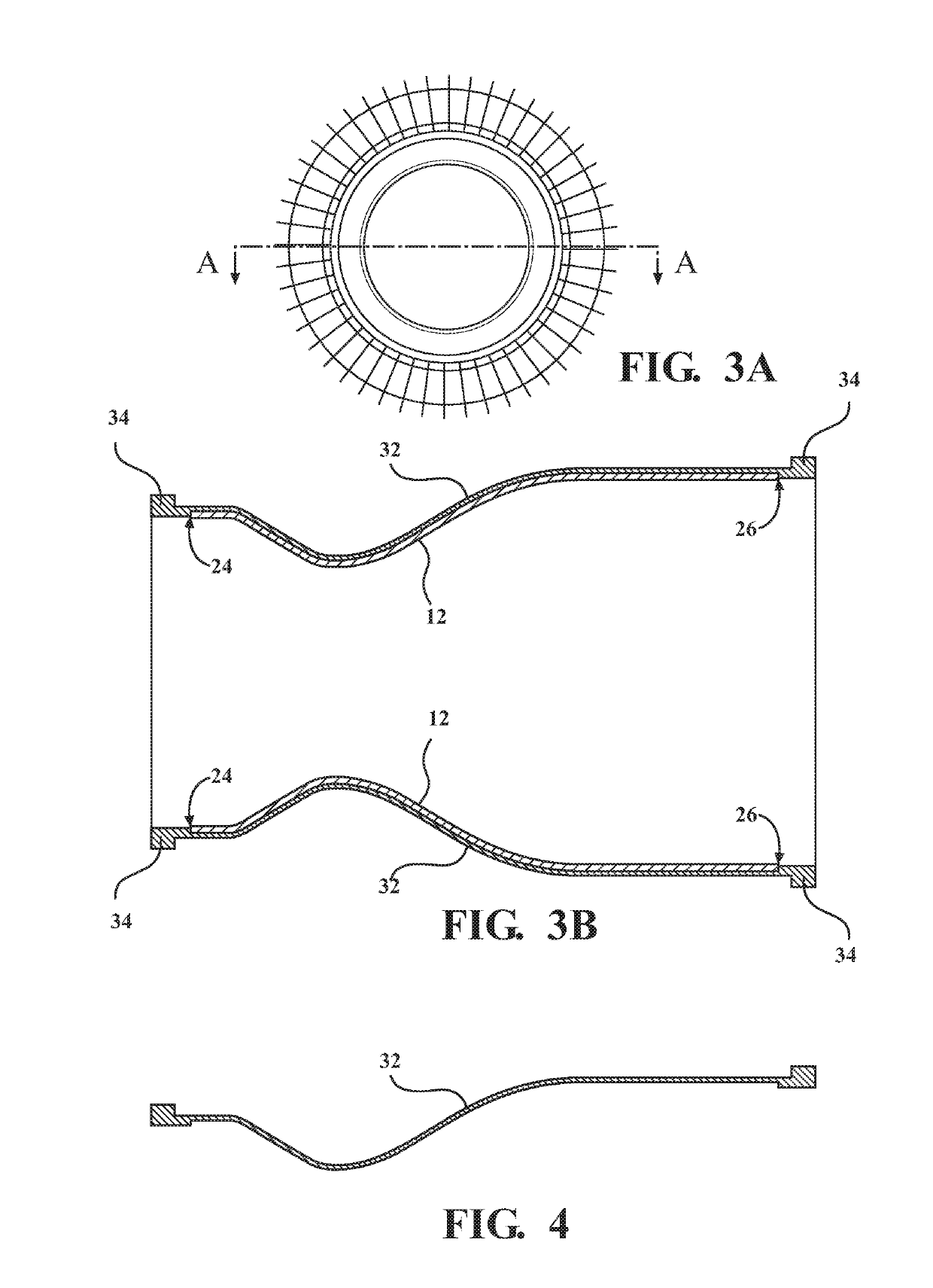
[0027]A method of producing a component, e.g. a metal aerospace component such as a thrust chamber, is disclosed herein. Referring now to the drawings, wherein like numerals indicate corresponding parts throughout the several views, the method is generally shown at 8 and the component is generally shown at 10. The component 10 includes a base structure, generally indicated at 12, and an additive structure 14 integral with the base structure 12. In the representative embodiments illustrated herein and depicted throughout the drawings, the component 10 is exemplified as a thrust chamber 10 which includes the base structure 12 and an additive structure 14 integral with the base structure 12. FIG. 1 is a side view of a thrust chamber 10 produced with the method 8 of the subject disclosure. Those having ordinary skill in the art will appreciate that the component 10 could be realized in a number of different configurations / designs, in a number of different components 10, for different ap...


PUM

PropertyMeasurementUnit
thicknessaaaaaaaaaa
mean particle sizeaaaaaaaaaa
thicknessaaaaaaaaaa

Abstract

A method of producing a component is disclosed. The method first comprises the steps of providing a base structure having a surface, providing an exoskeleton, and positioning the exoskeleton about the surface of the base structure. Once the exoskeleton is positioned, the method further comprises the steps of depositing metallic material on the surface of the base structure having the exoskeleton thereabout with an additive manufacturing process to form an additive structure, and removing the exoskeleton to form one or more cavities within the component and complete production thereof

Description

CROSS REFERENCE TO RELATED APPLICATIONS[0001]The subject application claims priority to and all the benefits of U.S. Provisional Patent Application No. 62 / 644,966, filed on Mar. 19, 2018, the contents of which are expressly incorporated herein in their entirety.TECHNICAL FIELD[0002]The present invention relates, generally, to a method of producing components with additive manufacturing and the components produced therewith.BACKGROUND[0003]Metal components of complex geometry, e.g. aerospace components, having various shapes and internal passages and cavities therein may be difficult to forge, cast, mill, machine, weld, braze, or otherwise produce. In fact, many such metal components are design limited by conventional production methods. Further, conventional production methods can be time-consuming and expensive, and can yield metal components of varying dimensional integrity and quality. In the aerospace industry, there is a need for efficient production of metal components which a...

Claims


Application Information

Patent Timeline
Patent Type & Authority Applications(United States)
IPC IPC(8): B22F3/105B22C9/24B22F3/24
CPCB33Y10/00B22F2003/1056B22F2003/247B22F3/1055B33Y80/00B22C9/24B22F3/24B33Y30/00B22F2998/10B22F7/08B33Y50/02Y02P10/25B22F10/43B22F10/62B22F10/28B22F10/66B22F10/25B22F12/90F02K9/64B29C64/153B29C64/40
Inventor RUPPENTHAL, KURT DAVIDCANUMALLA, RAMACHANDRACLARK, DAVID ANTHONYPERUBANDI, DAYAKARA RAJU
Owner WELDALOY PROD CO
Why Eureka
Try Eureka