Perpendicular magnetic recording medium

a magnetic recording medium and perpendicular technology, applied in the field of magnetic recording mediums, can solve the problems of random crystal growth in random directions, the grain isolation property of magnetic crystal grains decreases,

Inactive Publication Date: 2019-09-19
FUJI ELECTRIC CO LTD +1
View PDF1 Cites 3 Cited by
  • Summary
  • Abstract
  • Description
  • Claims
  • Application Information

AI Technical Summary

Benefits of technology

[0005]In the aforementioned perpendicular magnetic recording medium described in International Publication No. WO2015/087510, ZnO is introduced as the second non-magnetic portion of th

Problems solved by technology

However, the perpendicular magnetic recording medium as described above has a problem that, when the magnetic recording layer is formed to be thick and have a film thickness of, for example, 5 nm or more by forming the first magnetic recording layer 51b

Method used


Image

  • Perpendicular magnetic recording medium
  • Perpendicular magnetic recording medium
  • Perpendicular magnetic recording medium

Examples


example 1

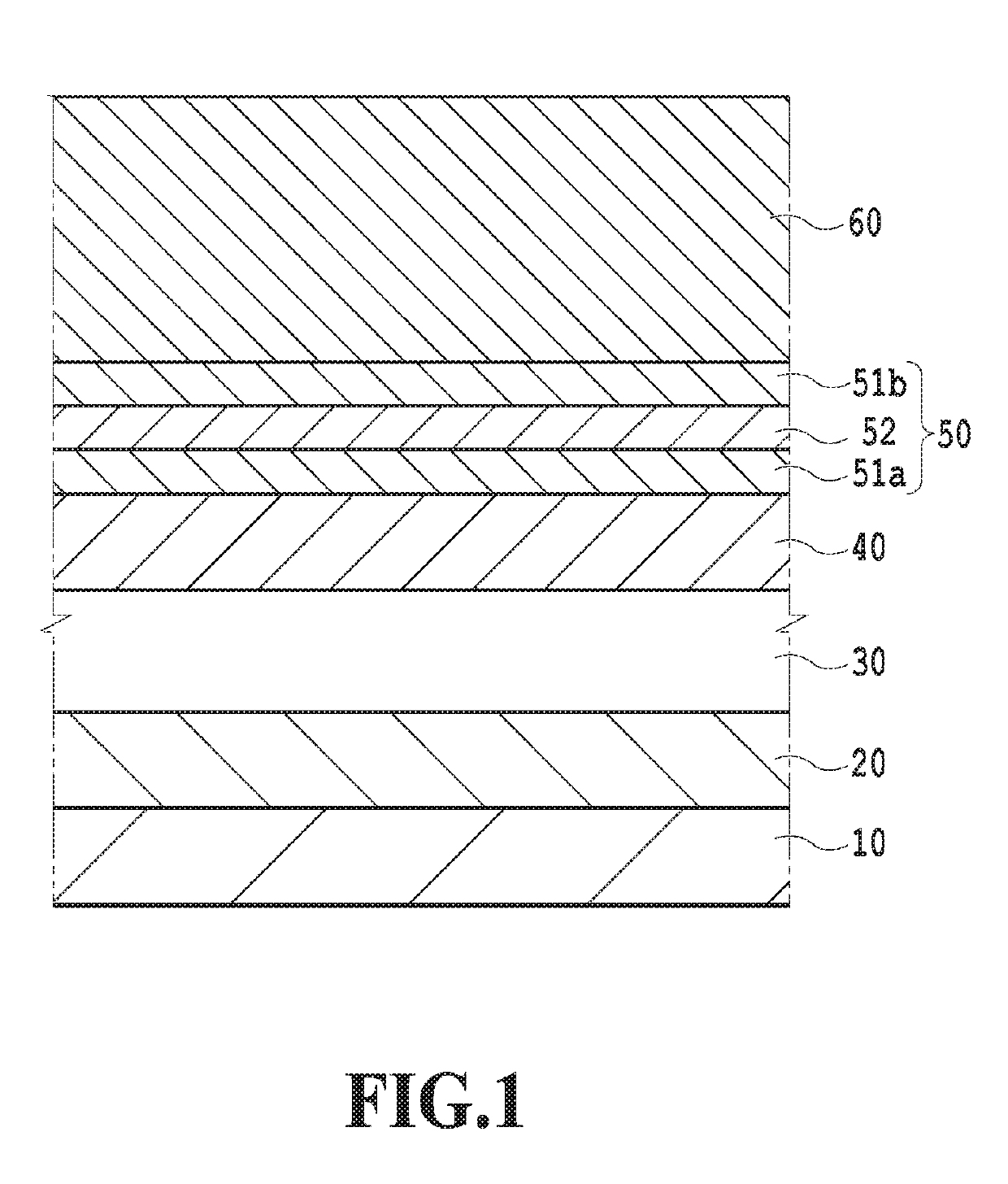
[0067]A chemically strengthened glass substrate with a smooth surface (N-10 glass substrate manufactured by Hoya Corporation) was cleaned to prepare the non-magnetic substrate 110. The cleaned non-magnetic substrate 110 was introduced into a sputtering apparatus. A DC magnetron sputtering method using a pure Ta target was performed in an Ar gas at a pressure of 0.3 Pa to form the adhesion layer 120 made of Ta and having a film thickness of 5 nm.

[0068]The laminate in which the adhesion layer 120 was formed was subjected to a RF sputtering method using a MgO target in the Ar gas at a pressure of 0.1 Pa to form the intermediate layer made of MgO and having a film thickness of 1 nm. The applied RF power was 200 W.

[0069]Next, a DC magnetron sputtering method using a pure Cr target was performed in the Ar gas at a pressure of 0.3 Pa to form the underlying layer 130 made of Cr and having a film thickness of 20 nm.

[0070]Then, the substrate was heated to 400° C. and a RF sputtering method us...

example 2

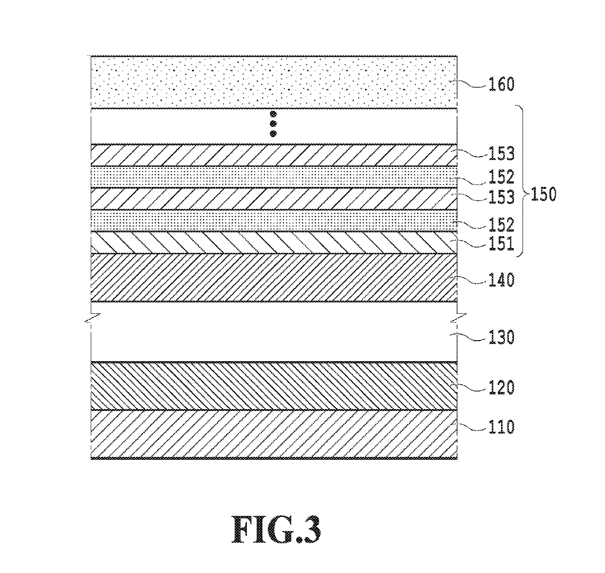
[0077]The adhesion layer 120, the intermediate layer, the underlying layer 130, and the seed layer 140 were sequentially formed over the non-magnetic substrate 110 as in Example 1 described above.

[0078]Next, as in Example 1 described above, the first magnetic recording layer 151 was formed on the laminate in which the seed layer 140 was formed and then the second magnetic recording layer 152 and the third magnetic recording layer 153 described above were formed. Furthermore, alternate stacking of the second magnetic recording layer 152 and the third magnetic recording layer 153 described above were repeated in the same conditions as those in Example 1 described above. Three second magnetic recording layers 152 and three third magnetic recording layers 153 were thereby alternately stacked over the first magnetic recording layer 151 and the magnetic recording layer 150 with a total film thickness of 11 nm was formed.

[0079]Finally, a DC magnetron sputtering method using a Pt target was...

example 3

[0082]The volume ratio x2 / x3 of the volume fraction x2 of the second non-magnetic portion just after the formation to the volume fraction x3 of the third non-magnetic portion and the film thickness ratio t2 / t3 of the film thickness t2 of the second magnetic recording layer 152 to the film thickness t3 of the third magnetic recording layer 153 which are illustrated in FIG. 6 were studied as described below to explain the results obtained by evaluating the state of the crystal grains of the magnetic recording medium and the state of order. First, the method of forming samples with various volume fractions x2, x3 and various film thicknesses t2, t3 is described and then results of evaluating these samples are described.

(Sample Forming)

[0083]First, the adhesion layer 120, the intermediate layer, the underlying layer 130, and the seed layer 140 were sequentially formed over the non-magnetic substrate 110 as in Example 1 described above.

[0084]Then, the magnetic recording layer 150 with th...


PUM


Abstract

In a perpendicular magnetic recording medium and a method of manufacturing the same, a first magnetic recording layer includes first magnetic crystal grains and a first non-magnetic portion containing carbon, a second magnetic recording layer includes second magnetic crystal grains and a second non-magnetic portion containing ZnO, a third magnetic recording layer includes third magnetic crystal grains and a third non-magnetic portion containing carbon, a film thickness t2 of the second magnetic recording layer is 0.1 nm to 7.0 nm, a volume fraction x2 of the second non-magnetic portion in the second magnetic recording layer at completion of formation is 0.20 to 0.90, a film thickness t3 of the third magnetic recording layer is 0.5 nm to 4.0 nm, a volume fraction x3 of the third non-magnetic portion in the third magnetic recording layer is 0.20 to 0.70, and (t2/t3)×(x2/x3) is 0.30 to 1.20.

Description

CROSS-REFERENCES TO RELATED APPLICATIONS[0001]This application claims the benefit of the priority of Japanese Patent Application No. 2018-051303, filed Mar. 19, 2018, which is hereby incorporated by reference in its entirety.BACKGROUND OF THE INVENTION1. Field of the Invention[0002]The present invention relates to a magnetic recording medium, more specifically to a perpendicular magnetic recording medium using magnetic crystal grains with an ordered structure.2. Description of the Related Art[0003]In a technology of perpendicular magnetic recording in which magnetic crystal grains with an ordered structure such as an L10 ordered alloy is used in a magnetic recording layer, there is a magnetic recording layer having a granular structure which includes magnetic crystal grains containing the ordered alloy and a non-magnetic portion surrounding the magnetic crystal grains. For example, in a perpendicular magnetic recording medium including a magnetic recording layer containing carbon in...

Claims


Application Information

Patent Timeline
IPC IPC(8): G11B5/667G11B5/127G11B5/852
CPCG11B5/667G11B5/852G11B5/1278G11B5/65G11B5/66G11B5/82G11B5/7379G11B5/672
Inventor KATAOKA, HIROYASUKIKUCHI, HIROTOFURUTA, AKIRASHIMATSU, TAKEHITO
Owner FUJI ELECTRIC CO LTD
Why Eureka
Try Eureka