Pulsed power transmission apparatus

a transmission apparatus and power technology, applied in the direction of reducing harmonics/ripples, secondary cells servicing/maintenance, instruments, etc., can solve the problems of difficult to suppress radiation noise to satisfy the standard in a high frequency region, and increasing radiation noise from the wire harness. , to achieve the effect of reducing the harmonic component of the transmitted pulsed power waveform, reducing the radiation noise generated by the transmission line such as the wire harness, and facilitating

Active Publication Date: 2019-09-19
YAZAKI CORP
View PDF2 Cites 3 Cited by
  • Summary
  • Abstract
  • Description
  • Claims
  • Application Information

AI Technical Summary

Benefits of technology

[0023]According to the pulsed power transmission apparatus having the aforementioned configuration (4), the information indicating the kind of the power packet is included in the digital information. Thus, a plurality of power packets with different kinds of voltages etc. can be handled. In addition, when the information indicating the power consumption destination is included in the digital information, it is easy to change over power distribution paths from one to another power packet by power pac

Problems solved by technology

Therefore, radiation noise from the wire harness becomes an issue.
Accordingly, when pulsed power with a large ratio of the harmonic components is transmitted, it is difficult to suppress the radiation noise to satisfy the standard in a high frequency region.
Particularly when large power like power supply power is transmitted, there is a possibility that the radiation noise from the wire harness may increase as the power increases.
Accordingly, it is difficult to reduce the radiation noise.
However, when the pow

Method used


Image

  • Pulsed power transmission apparatus
  • Pulsed power transmission apparatus
  • Pulsed power transmission apparatus

Examples


Embodiment Construction

[0035]A specific embodiment about the present invention will be described below with reference to the respective drawings.

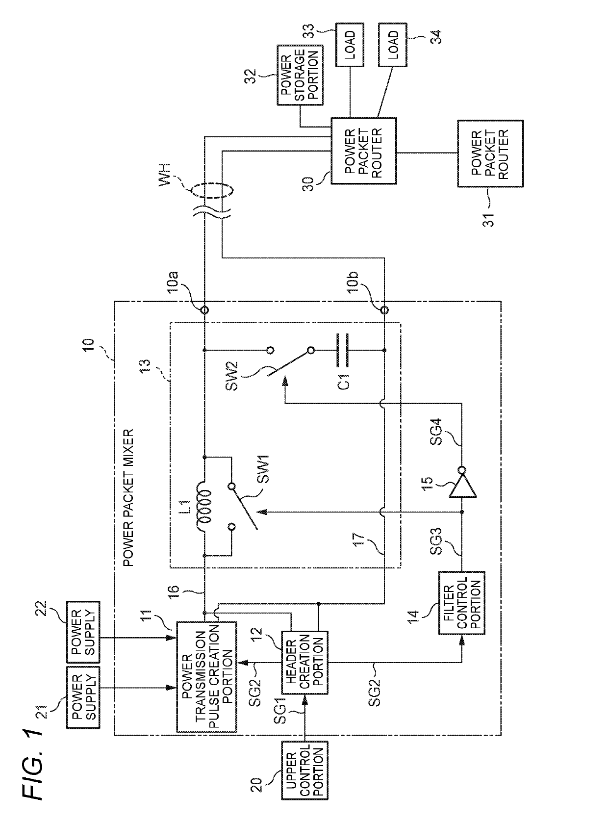
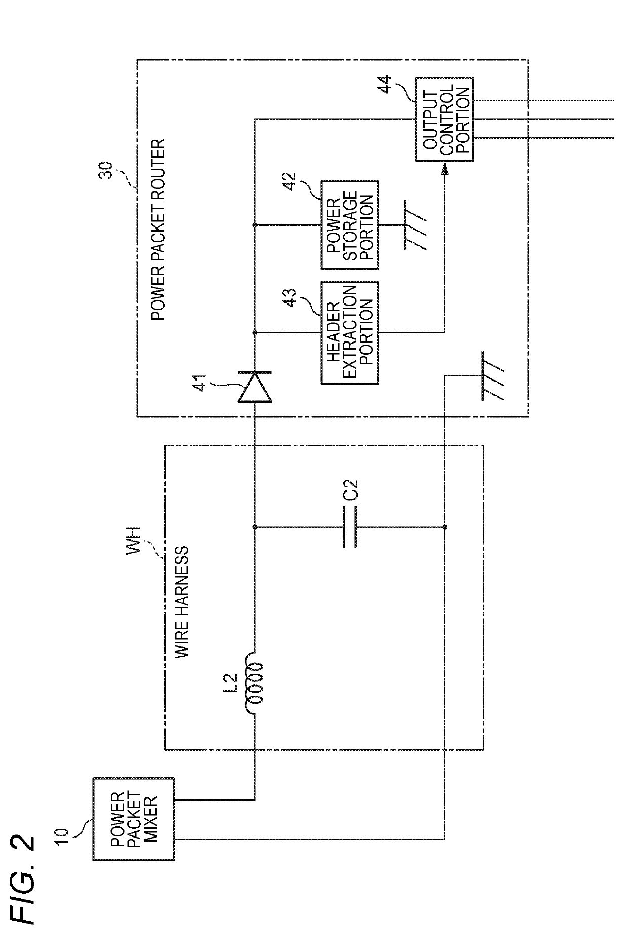
[0036]FIG. 1 is a block diagram showing a configuration example of a main portion of a pulsed power transmission system in the embodiment of the present invention. FIG. 2 is a block diagram showing a configuration example of a wire harness and a router.

[0037]It is assumed that the pulsed power transmission system shown in FIG. 1 is mounted on a vehicle and used for distributing power-supply power fed from an on-vehicle battery etc. to various loads on the vehicle, i.e. on-vehicle electrical components. It is a matter of course that the pulsed power transmission system may be used for any other application than the on-vehicle system, and the configuration of details of the pulsed power transmission system may be changed suitably if necessary.

[0038]The pulsed power transmission system shown in FIG. 1 is provided with a mixer 10 creating power packets, and routers 3...


PUM


Abstract

When a pulsed waveform is used to transmit power-supply power in a form of a power packet etc., a filter for reducing harmonic components is disposed on a power transmission side. A switch and a control portion for controlling ON/OFF of a function of the filter are provided to turn ON the function of the filter limitedly at each of timings t1 to t2 and t3 to t4 at which the power is transmitted. The harmonic components are reduced from the waveform of the transmission power by the function of the filter. Radiation noise generated by the wire harness is reduced in a high frequency region. The function of the filter is turned OFF at a timing at which digital information is transmitted so that a waveform of the digital information can be prevented from being deformed.

Description

CROSS REFERENCE TO RELATED APPLICATIONS[0001]This application is based on and claims priority from Japanese patent application No. 2018-045876 filed on Mar. 13, 2018, the entire contents of which are incorporated herein by reference.BACKGROUND OF THE INVENTION1. Technical Field[0002]The present invention relates to a pulsed power transmission apparatus that can be used, for example, for feeding power on a vehicle etc.2. Background Art[0003]Generally, an on-vehicle battery or an alternator (a power generator) serving as a main power supply, and various kinds of electrical components disposed on various places on a vehicle are connected to each other respectively via a wire harness serving as an assembly of electric wires. Accordingly, power stored by the on-vehicle battery is fed as power-supply power to the various electrical components.[0004]On the other hand, a technique for packetizing power and distributing and transmitting the packetized power has been disclosed, for example, i...

Claims


Application Information

Patent Timeline
IPC IPC(8): H02J13/00H02J1/02H02J1/10H01M10/44H04B10/524B60R16/02B60R16/023
CPCH02J13/0003H02J1/02H02J1/102B60R16/0207B60R16/023H04B10/524H01M10/44H02M1/44B60R16/03H02M1/15H02M3/155G07C9/00H02J13/00009H02J2310/40H02J2310/46Y02E60/10H02M1/0012H02M1/009H02J13/00001
Inventor KIMURA, OSAMU
Owner YAZAKI CORP
Why Eureka
Try Eureka