Floor panel and method for manufacturing a floor panel

a technology of floor panels and manufacturing methods, applied in the direction of flooring, floor coverings, synthetic resin layered products, etc., can solve the problems of entanglement of floor panels, high risk of telegraphy effects, and high risk of pushed-up edges and/or gaps between mutually coupled panels, so as to increase the dimensional stability of the substrate layer, the effect of positive effect on the dimensional stability of the panel

Active Publication Date: 2019-09-26
FLOORING IND LTD
View PDF21 Cites 24 Cited by
  • Summary
  • Abstract
  • Description
  • Claims
  • Application Information

AI Technical Summary

Benefits of technology

[0007]It is noted that by the term substrate reference is made to that portion of the floor panel which is situated underneath the decor or the possible decor carrier.
[0008]The rigidity of the substrate layer preferably is obtained by making the thermoplastic material thereof rigid. This is possibly by using an appropriate amount of plasticizer or no plasticizers at all. If plasticizers are used, this preferably is in an amount of less than 15 phr, less than 10 phr or less than 5 phr. It is noted that an amount of plasticizers of less than 15 phr means that per 100 parts of thermoplastic synthetic material less than 15 parts of plasticizers are present. Examples of plasticizers which can be applied are phthalate-based plasticizers, such as di-isononyl phthalate, abbreviated DINP, or di-octyl phthalate, abbreviated DOP or DnOP, or, as an alternative for phthalate-based plasticizers, di-octyl terephthalate, abbreviated DOTP, or di-isononyl-1, 2-cyclohexane dicarboxylate, abbreviated DINCH.
[0009]The thermoplastic material of th

Problems solved by technology

However, such floor panel entrains a number of problems.
For example, there is a not to be neglected risk of telegraphy effects.
When installing the panels in a room with much incident sunlight, such as a veranda or the like, there is also a high risk of the occurrence of pushed-up edges and/or the formation of gaps between the mutually coupled panels.
Although the use of a glass fiber layer may increase the dimensional stability of the floor panel, this often still has proven insufficient in order to avoid the last-mentioned problems.
Moreover, the panels are relatively flexible and bendable, due to which the installation thereo

Method used


Image

  • Floor panel and method for manufacturing a floor panel
  • Floor panel and method for manufacturing a floor panel
  • Floor panel and method for manufacturing a floor panel

Examples


Embodiment Construction

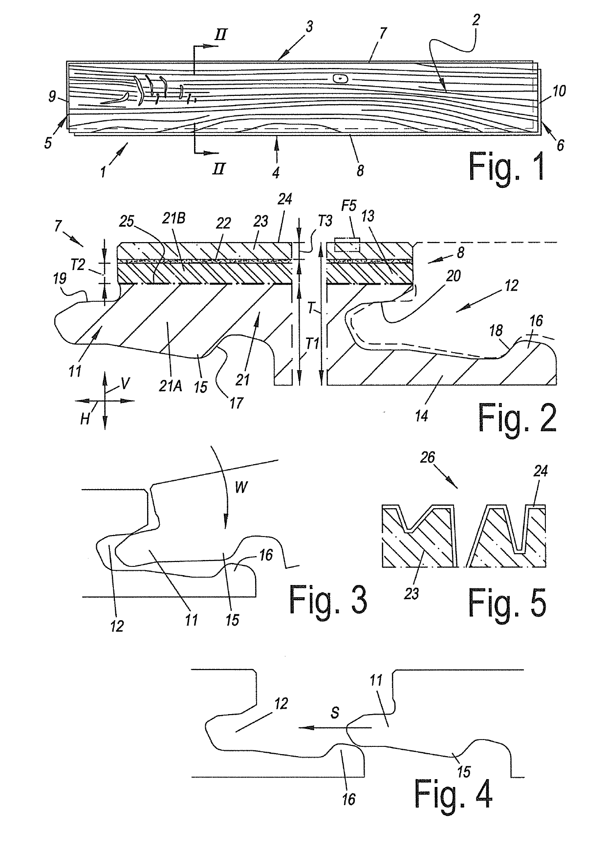
[0148]FIG. 1 represents a floor panel 1 according to the invention. The represented floor panel 1 comprises a decor 2, which relates to printed wood decor. This relates to an oblong rectangular floor panel 1, which as a result has a pair of long edges 3-4 and a pair of short edges 5-6. Each pair of edges is provided with coupling parts, which are indicated by the reference numbers 7-8 and 9-10, respectively.

[0149]The shape of the coupling parts 7-8 is evident from FIG. 2. This relates to a tongue and groove connection comprising a tongue 11 and a groove 12, the groove being bordered by an upper lip 13 and a lower lip 14. The lower lip 14 protrudes to beyond the upper lip 13. Additionally, the connection comprises locking elements 15-16, in the form of a protrusion 15 on the lower side of the tongue 11 and an upward-directed locking element 16 in the portion of the lower lip 14 that protrudes beyond the upper lip 13, which, by cooperating locking surfaces 17-18, counteract the moving...


PUM

PropertyMeasurementUnit
Percent by massaaaaaaaaaa

Abstract

Floor panel with a substrate, including thermoplastic material, a decor provided thereon, and, on at least one pair of opposite edges, coupling parts realized at least partially from the substrate. The coupling parts allow to effect a mechanical locking between two of floor panels, where the substrate includes a rigid substrate layer of thermoplastic material, and a glass fiber layer is present in the floor panel.

Description

CROSS REFERENCE TO RELATED APPLICATIONS[0001]This application claims the benefit under 35 U.S.C. 119(e) to the U.S. provisional applications U.S. 62 / 420,094 filed on Nov. 10, 2016, which is incorporated herein by reference.[0002]This invention relates to a floor panel and to a method for manufacturing a floor panel. More particularly, the invention relates to a floor panel of the type which comprises a substrate comprising thermoplastic material, and a decor provided thereon, as well as, on at least one pair of opposite edges, coupling parts realized at least partially from the substrate, said coupling parts allowing to effect a mechanical locking, i.e. without using glue or the like, between two of such floor panels. This type of floor panels allows forming a waterproof floor covering in a smooth and user-friendly manner. Such floor covering may also be applied without any problems in humid rooms, such as bathrooms, contrary to wood-based laminate floor panels with, for example, a ...

Claims


Application Information

Patent Timeline
IPC IPC(8): E04F15/02B29C70/08E04F15/10
CPCE04F15/02038B29C70/08E04F15/105B32B27/30E04F2201/0146E04F2201/0153E04F2201/0552E04F15/107E04F2201/023E04F2201/027B32B5/02B32B5/16B32B5/18E04F15/10B32B2264/0242B32B2266/0235B32B2419/04B32B2471/00E04F2290/042B29D99/0057B32B2264/108B32B9/02B32B2260/028B32B27/304B32B3/06B32B27/12B32B2255/10B32B7/12B32B2307/412B32B27/22B32B27/40B32B27/32B32B2307/51B32B2260/021B32B5/022B32B2260/046B32B2266/025B32B2307/72B32B27/065B32B2264/067B32B5/028B32B2607/00B32B27/20B32B9/045B32B2307/554B32B27/36B32B2307/102B32B2264/102B32B29/005B32B25/08B32B2307/546B32B2262/101B32B2264/107B32B2307/718B32B27/08B32B17/02B32B5/024B29C70/086B29K2027/06B29K2105/04B29K2309/08B29L2031/732B32B5/245B44C5/0407
Inventor VAN VLASSENRODE, KRISTOFBRUSSEEL, PAULVANHULLE, NICKBOSSUYT, JOCHEN
Owner FLOORING IND LTD
Why Eureka
Try Eureka