Eureka AIR delivers breakthrough ideas for toughest innovation challenges, trusted by R&D personnel around the world.

System and method for dual speed resolver

Active Publication Date: 2019-09-26
THE BOEING CO
View PDF0 Cites 6 Cited by
  • Summary
  • Abstract
  • Description
  • Claims
  • Application Information

AI Technical Summary

Benefits of technology

The patent describes an apparatus and method for accurately positioning a motor's shaft using a combination of coarse and fine position signals. The apparatus includes a coarse resolver and a fine resolver to provide the position signals. The method involves receiving the position signals, comparing them to a reference position, and generating an initial position output based on the coarse position signals. The apparatus and method can be used in a feedback control system to adjust the motor's position. The technical effects of the patent include improved accuracy in motor positioning and improved control system performance.

Problems solved by technology

Additionally, interference from current switching during operating the gimbal motors can add noise and errors.
Reduced precision and errors accumulate over time in inertial navigation and can lead to incorrect data or navigation.
However, these solutions do not generally provide increased precision and increased bandwidth simultaneously.
Additionally, these solutions add complexity, cost, weight, and volume to vehicle design.
In the context of flying vehicles (aircraft, spacecraft, etc.), weight and volume greatly increase cost and reduce performance.
However, the output of the coarse resolver has less accuracy and precision than the fine resolver and utilizing both the coarse and fine outputs reduces the accuracy and precision of the dual resolver to less than the accuracy of the fine resolver.
However, multiplying the digital samples by the excitation signal generates noise.
To illustrate, multiplying sine values of angles together reduces accuracy of the data between peaks of the sine waves, i.e., it squares any noise or errors.
However, taring has reduced effects (reduced improvements) and less precise taring may be used when reducing noise due to time coordination of excitation signals and current drive switching, when dither is added to the excitation signal, or both, as described with reference to FIGS. 22-28.

Method used


Image

  • System and method for dual speed resolver
  • System and method for dual speed resolver
  • System and method for dual speed resolver

Examples


Embodiment Construction

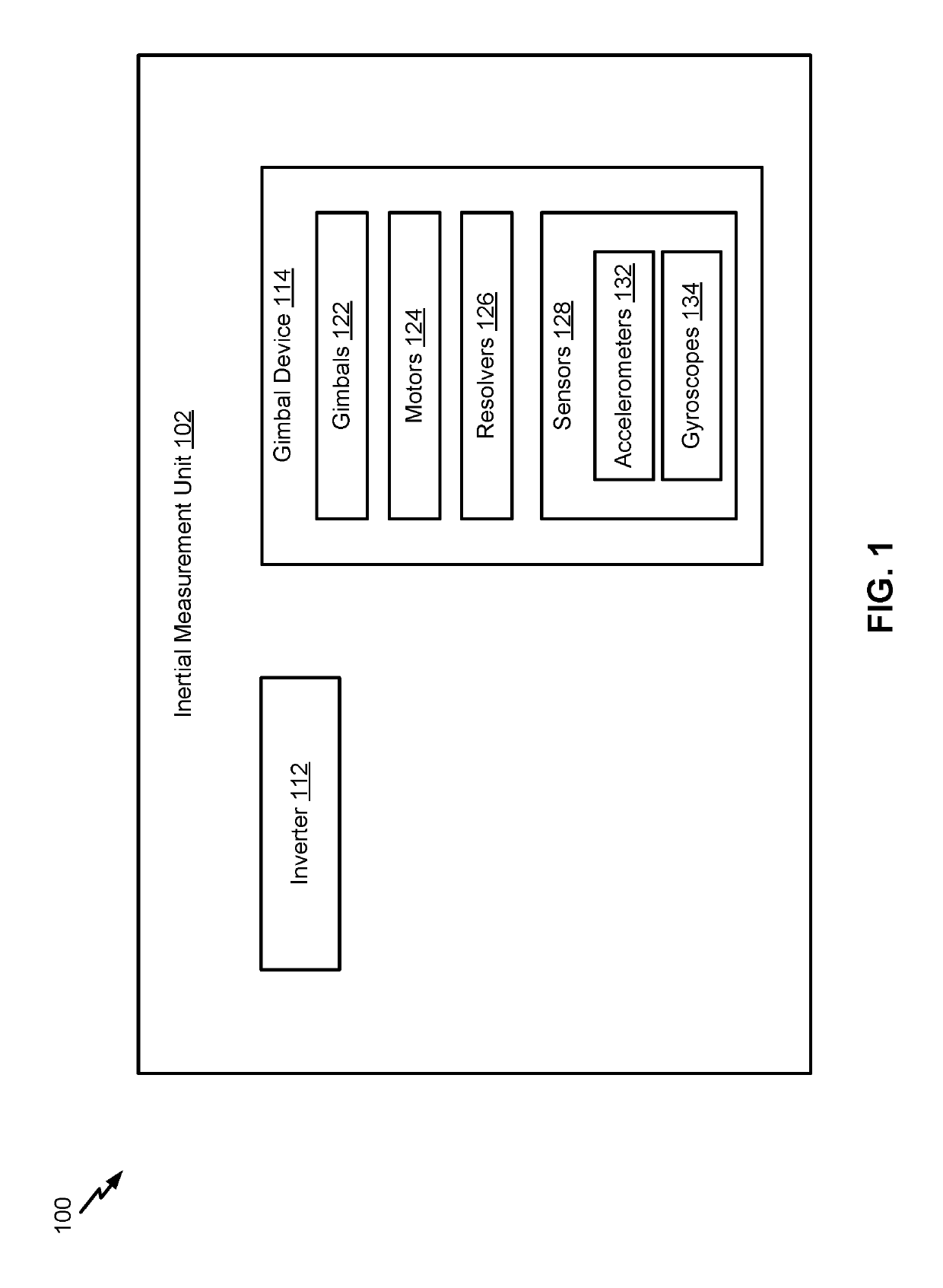
[0064]Implementations disclosed herein are directed to gimbaled inertial measurement units. A gimbaled inertial measurement unit includes sensors, such as accelerometers and gyroscopes, to determine vehicle inertia data, such as linear acceleration and angular velocity. In a gimbaled inertial measurement unit, an inertial measurement unit is mounted on a multi-axis gimbal device. The gimbal device includes multiple gimbals each with a corresponding motor. The motors are used to drive and position the gimbals such that the sensors are oriented along the vehicle's path. A control system of the vehicle tracks the position of the vehicle based on outputs from the sensors as the gimbals move based on changes in inertia of the vehicle. The control system then outputs commands to the gimbaled inertial measurement unit to adjust (readjust) the sensors such that the sensors are oriented along the vehicle's updated path.

[0065]In some implementations, the gimbaled inertial measurement unit use...


PUM


Abstract

An apparatus includes a coarse resolver configured to output coarse position signals indicative of a coarse position of a drive shaft of a motor. The apparatus also includes a fine resolver configured to output fine position signals indicative of a fine position of the drive shaft of the motor. The apparatus further includes a control circuit. The control circuit is configured to receive the coarse position signals from the coarse resolver and the fine position signals from the fine resolver and generate an initial position output, based on the coarse position signals, that indicates an initial position of the drive shaft. The control circuit is further configured to generate a subsequent position output, based on the fine position signals, that indicates a subsequent position of the drive shaft.

Description

FIELD OF THE DISCLOSURE[0001]The present disclosure is generally related to dual speed resolvers and gimbaled inertial measurement units.BACKGROUND[0002]A gimbaled inertial measurement unit is used for vehicle navigation and object tracking. The gimbaled inertial measurement unit includes multiple gimbals that each rotate along a single axis to position sensors along the vehicle's path. By using multiple gimbals, such as three or four gimbals, a vehicle's inertia can be monitored in multiple axes by the sensors and used for inertial navigation. Inertial navigation continuously calculates by dead reckoning the position, the orientation, and the velocity of a moving object without the need for external reference. Dead reckoning (or deductive reckoning) involves calculating the vehicle's current position by using a previously determined position and advancing that position based upon estimated speeds and headings.[0003]Gimbaled inertial measurement units include additional sensors, suc...

Claims


Application Information

Patent Timeline
IPC IPC(8): G01C21/16G01C25/00H02P6/17H03M1/48
CPCH03M1/485H02P6/17G01C25/005G01C21/16H03M1/14H03M1/0639G01C19/16H02P6/16G01D5/2073G01D5/2046G01D3/02G01C21/188
Inventor CAMERON, DOUGLAS C.MERNA, DWAYNE C.SHARMA, MANU
Owner THE BOEING CO
Why Eureka
Eureka Blog
Learn More