Hydrogen supply system
a technology of hydrogen pump and supply system, which is applied in the direction of electrochemical generator, electrolysis components, separation processes, etc., can solve the problems of insufficient consideration and increase in power consumption amount, and achieve the effect of increasing the power consumption amount of the electrochemical hydrogen pump
- Summary
- Abstract
- Description
- Claims
- Application Information
AI Technical Summary
Benefits of technology
Problems solved by technology
Method used
Image
Examples
embodiments
[System Structure]
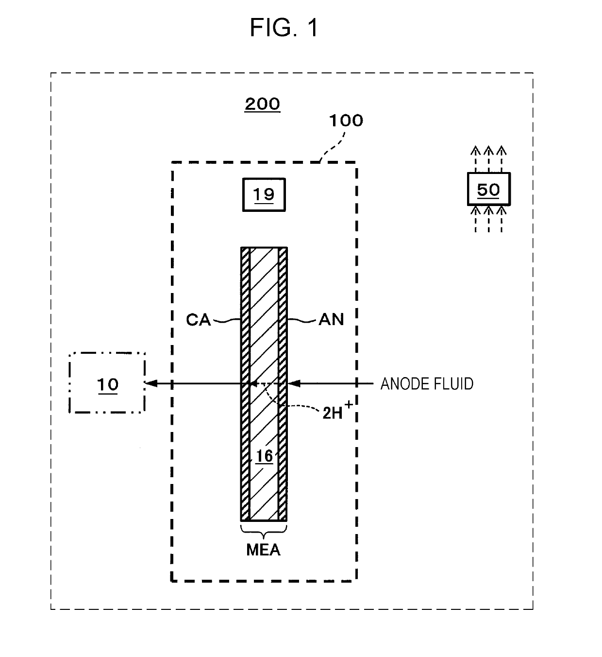
[0030]FIG. 1 is a schematic view showing one example of a hydrogen supply system of an embodiment.
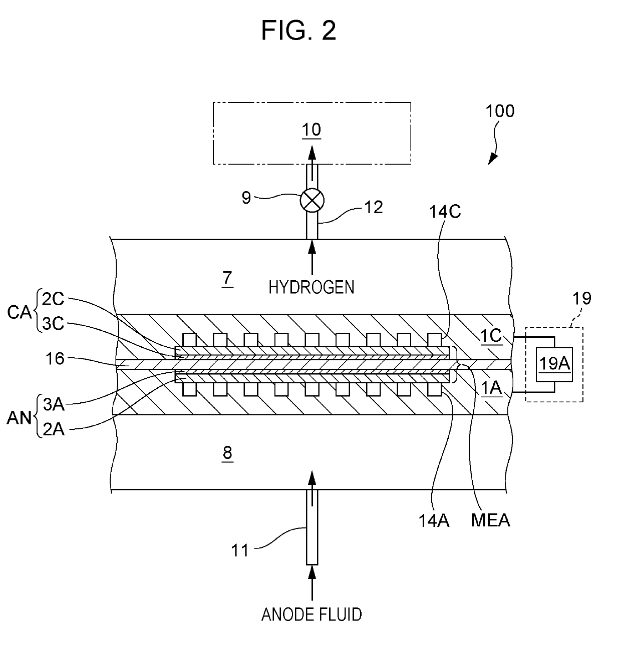
[0031]In the example shown in FIG. 1, a hydrogen supply system 200 includes an electrochemical hydrogen pump 100 and a controller 50. In this example, the electrochemical hydrogen pump 100 includes an electrolyte membrane 16, an anode AN, a cathode CA, and a current adjuster 19. In addition, as shown by a two-dot chain line of FIG. 1, together with the hydrogen supply system 200, a hydrogen storage device 10 may also be provided in some cases.
[0032]The electrolyte membrane 16 may have any structure as long as being an electrolyte membrane having a proton conductivity. As the electrolyte membrane 16, for example, a high molecular weight electrolyte membrane or a solid oxide membrane may be mentioned. In addition, as the high molecular weight electrolyte membrane, for example, a fluorine-based high molecular weight electrolyte membrane may be mentioned. In particular, fo...
first example
[0072]A hydrogen supply system 200 of a first example is similar to the hydrogen supply system 200 of the embodiment except for the following current control.
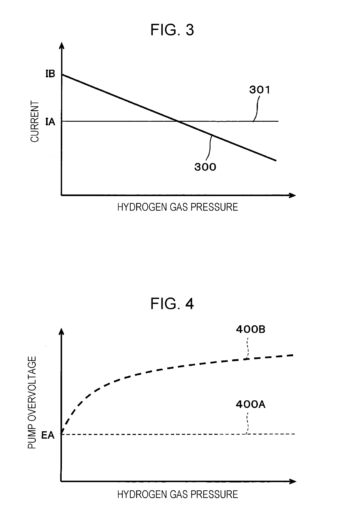
[0073]FIG. 3 is a graph showing one example of a current control of a current flowing between an anode and a cathode of an electrochemical hydrogen pump of the hydrogen supply system of the first example of the embodiment. The horizontal axis of FIG. 3 indicates a cathode gas pressure at a cathode CA side of an electrochemical hydrogen pump 100. The vertical axis of FIG. 3 indicates the current flowing between an anode AN and a cathode CA of the electrochemical hydrogen pump 100.
[0074]FIG. 3 shows a thick solid line (hereinafter, referred to as “current graph 300 of Example”) indicating the current flowing between the anode AN and the cathode CA of the electrochemical hydrogen pump 100 of the hydrogen supply system 200 of the first example. In addition, as a comparative example, a thin solid line (hereinafter, referred to as “c...
second example
[0096]A hydrogen supply system 200 of a second example is similar to the hydrogen supply system 200 of the embodiment except for the following current control.
[0097]FIG. 8 is a graph showing one example of a current control of a current flowing between an anode and a cathode of an electrochemical hydrogen pump of the hydrogen supply system of the second example of the embodiment. The horizontal axis of FIG. 8 indicates a cathode gas pressure at a cathode CA side of an electrochemical hydrogen pump 100. The vertical axis of FIG. 8 indicates a current flowing between an anode AN and a cathode CA of the electrochemical hydrogen pump 100.
[0098]FIG. 8 shows a thick solid line (hereinafter, referred to as “current graph 800 of Example”) indicating the current flowing between the anode AN and the cathode CA of the electrochemical hydrogen pump 100 of the hydrogen supply system 200 of the second example. In addition, as a comparative example, a thin solid line (hereinafter, referred to as “...
PUM
 Abstract
Description
Claims
Application Information
 - R&D
- Intellectual Property
- Life Sciences
- Materials
- Tech Scout
- Unparalleled Data Quality
- Higher Quality Content
- 60% Fewer Hallucinations
Browse by: Latest US Patents, China's latest patents, Technical Efficacy Thesaurus, Application Domain, Technology Topic, Popular Technical Reports.
© 2025 PatSnap. All rights reserved.Legal|Privacy policy|Modern Slavery Act Transparency Statement|Sitemap|About US| Contact US: help@patsnap.com


