

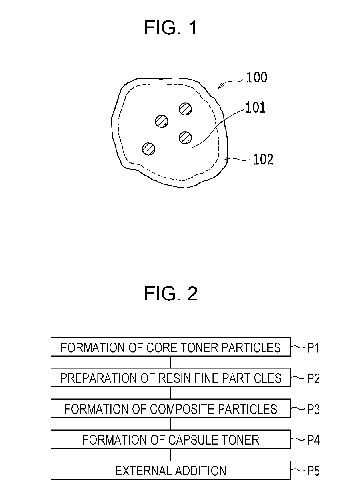
Capsule toner, two-component developer, image forming apparatus, and method for producing capsule toner
a technology of image forming apparatus and capsule toner, which is applied in the field of capsule toner, two-component developer, image forming apparatus, and method for producing capsule toner, can solve problems such as degrading blocking resistance, and achieve the effects of avoiding fusion, improving stress resistance in developing tanks, and low temperature fixing properties
- Summary
- Abstract
- Description
- Claims
- Application Information
AI Technical Summary
Benefits of technology
Problems solved by technology
Method used
Image

Examples
example 1
(1) Formation of Core Toner Particles (P1)
[0063]To a reactor of 5 L maintained at an inner temperature of 180° C. and an inner pressure of 6 kg / cm2, 20 parts by weight of a xylene solution, prepared by uniformly dissolving 1.5 parts by weight of di-tert-butyl peroxide in a solution containing 74 parts by weight of styrene, 26 parts by weight of n-butyl acrylate, and 80 parts by weight of a xylene solvent, is continuously supplied at 750 mL / hour and polymerized to prepare a solution of a styrene-acrylic resin. Then, the solvent is distilled off by flashing in a vessel at 90° C. and 10 mmHg, and then the residue is roughly ground by using a rough grinder to produce 1-mm chips of styrene-acrylic resin R-1 (refer to Table 1). Then, 5 parts by weight of carbon black (trade name: MA-100, manufactured by Mitsubishi Chemical Co., Ltd.) and 4 parts by weight of a release agent (trade name: Fischer-Tropsch wax, manufactured by Nippon Seiro Co., Ltd., melting point: 95° C.) are weighed relativ...
examples 2 to 16
[0071]Capsule toners T-2 to T-11 of Examples 2 to 11 are produced by the same method as in Example 1 except that the type and amount of the resin fine particles added are changed as shown in Table 4.
[0072]Also, capsule toners T-12 to T-16 of Examples 12 to 16 are produced by the same method as in Example 1 except that the type the core toner particles is changed as shown in Table 4.
TABLE 4Table 4 Capsule toner T-1 to T-16 (Example)Amount ofFormation ofCap-CoreResinresin finecapsule particlesuletonerfineparticle addedStirringtonerparticleparticleparts by weighttime minExample 1T-1C-1S-1710Example 2T-2S-2Example 3T-3S-3Example 4T-4S-4Example 5T-5S-5Example 6T-6S-6Example 7T-7S-7Example 8T-8S-8Example 9T-9S-9Example 10T-10S-15Example 11T-1115Example 12T-12C-27Example 13T-13C-3Example 14T-14C-4Example 15T-15C-5Example 16T-16C-6
PUM
 Abstract
Description
Claims
Application Information