

Driving substrate, manufacturing process, and micro-led array light-emitting backlight module
- Summary
- Abstract
- Description
- Claims
- Application Information
AI Technical Summary
Benefits of technology
Problems solved by technology
Method used
Image

Examples
Embodiment Construction
[0029]The following descriptions for the respective embodiments are specific embodiments capable of being implemented for illustrations of the present invention with referring to appended figures.
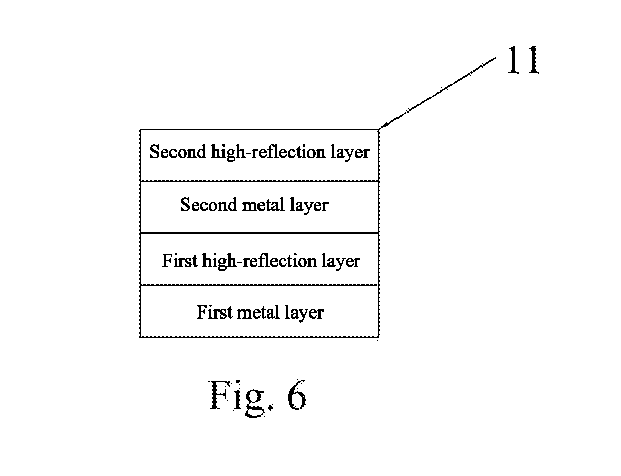
[0030]The driving substrate may be used in micro-LED array light-emitting backlight module. The driving substrate includes: a first metal layer, a first high-reflection layer, and a second metal layer stacked in a top-down sequence. The driving substrate may further includes an insulation supporting layer arranged between the first metal layer and the first high-reflection layer. The driving substrate may include at least a three-layer structure, having the first metal layer, the first high-reflection layer, and a second metal layer. Alternatively, the driving substrate may include at least a four-layer structure, having the first metal layer, the insulation supporting layer, the first high-reflection layer, and the second metal layer.
[0031]In one embodiment, the driving substrate may furth...
PUM
| Property | Measurement | Unit |
|---|---|---|
| Brightness | aaaaa | aaaaa |
| Reflection | aaaaa | aaaaa |
Abstract
Description
Claims
Application Information